

Antimicrobial substrate
a technology of antimicrobial substrate and substrate, which is applied in the field of antimicrobial substrate, can solve the problems of ptfe being difficult to process by conventional molten polymer techniques, affecting the stability of fabric, and affecting the production of artificial filaments
- Summary
- Abstract
- Description
- Claims
- Application Information
AI Technical Summary
Benefits of technology
Problems solved by technology
Method used
Image

Examples
example 1
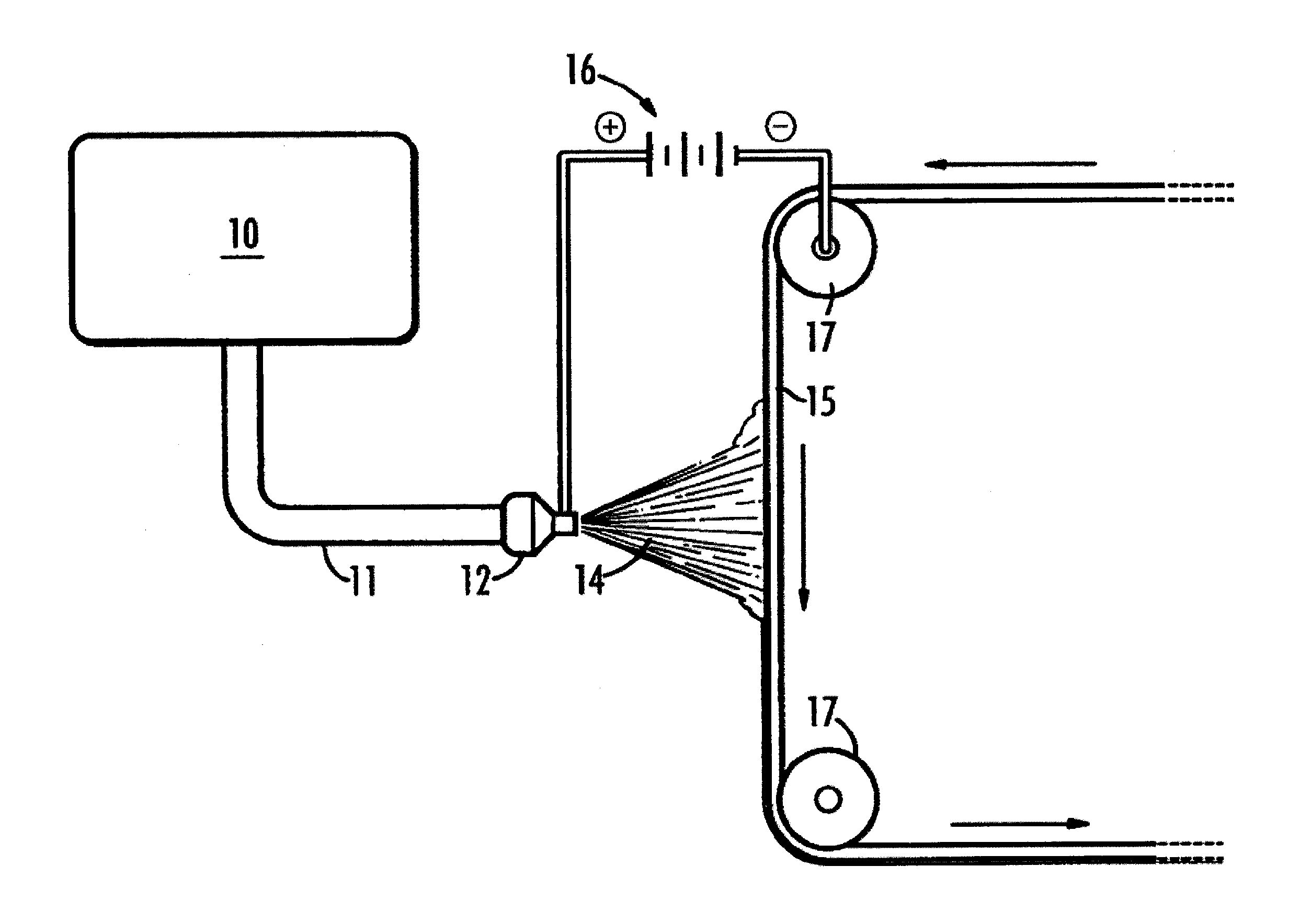
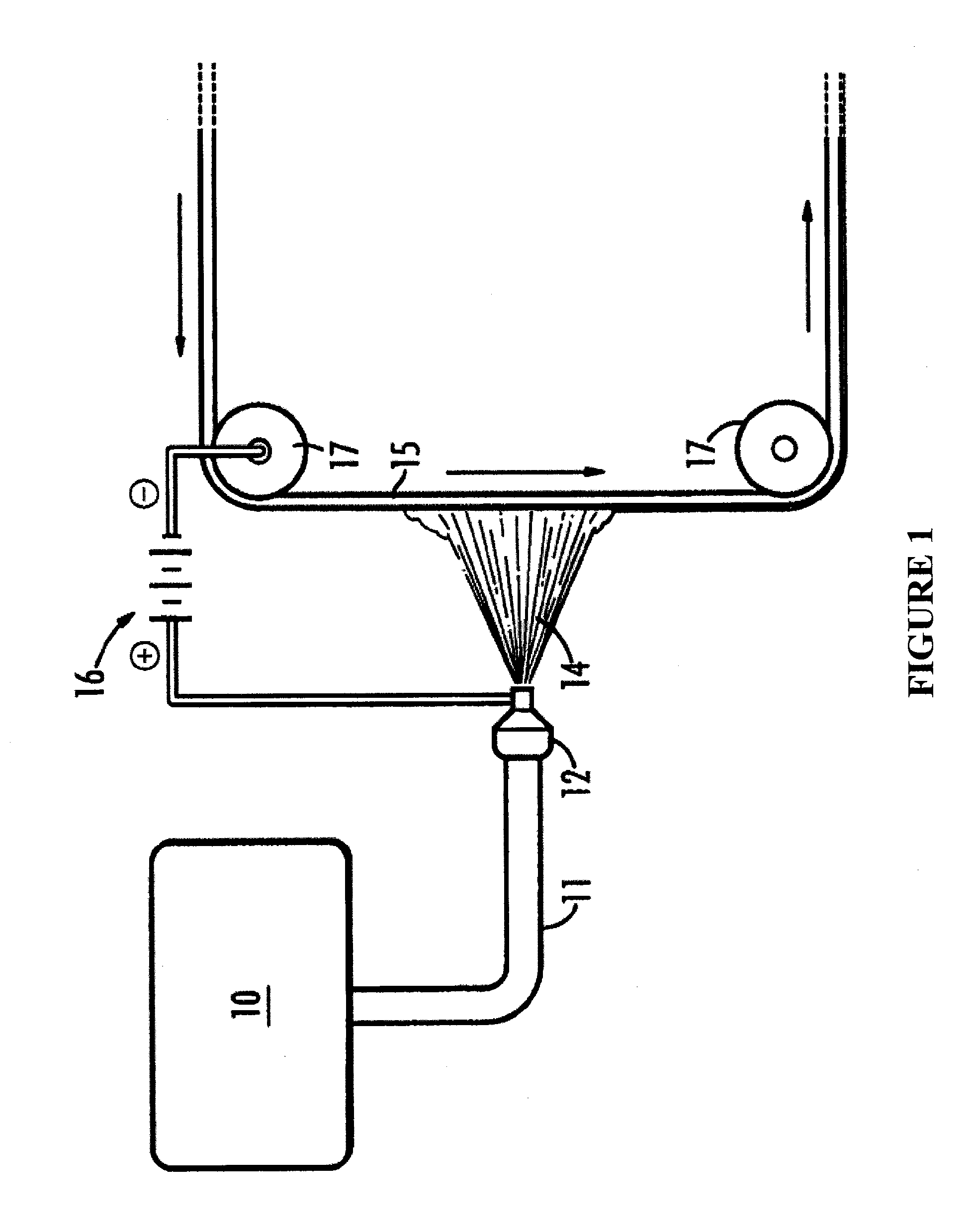
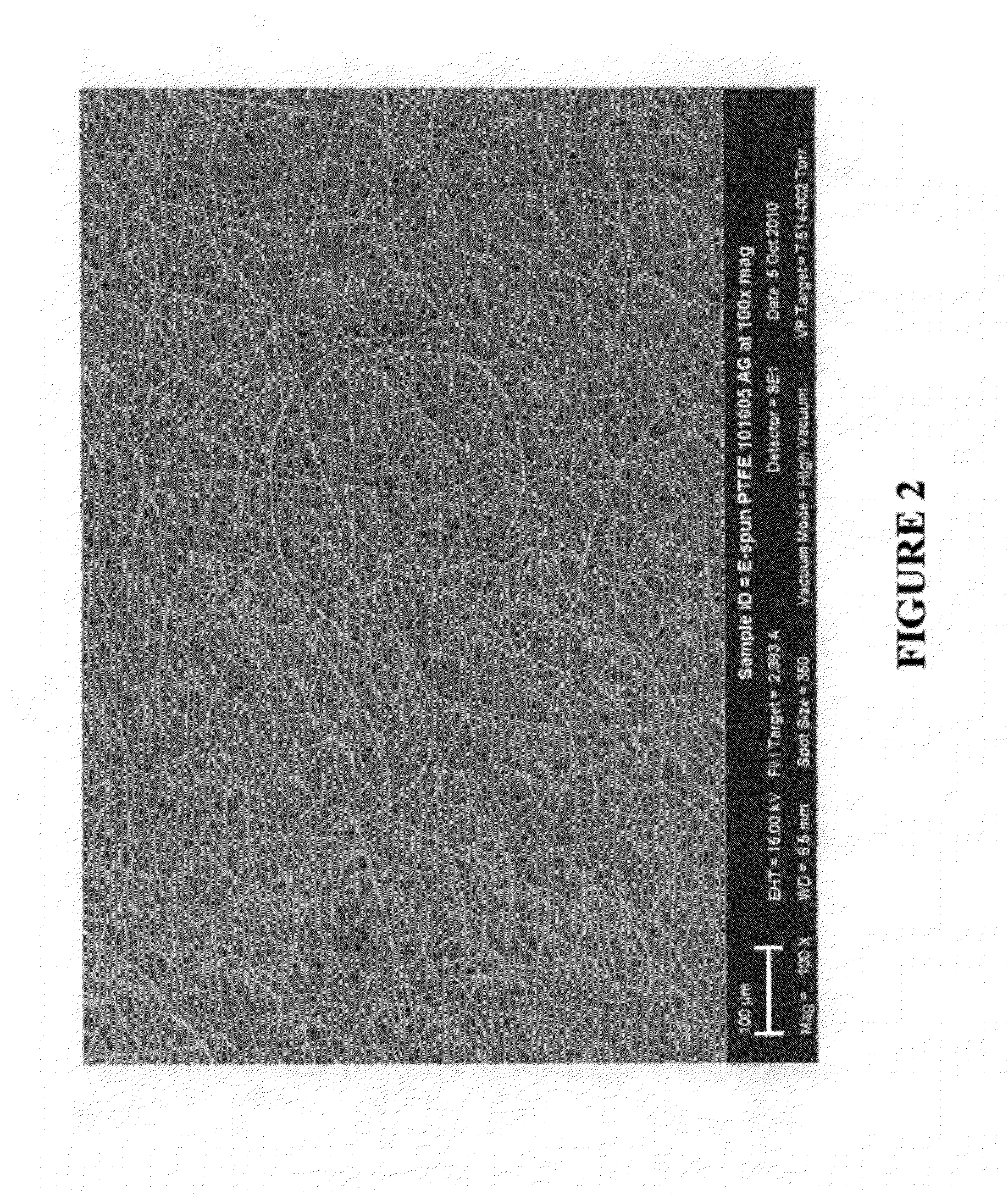
[0055]Fibers were made using an orifice (needle) based electrospinning apparatus. A stainless steel substrate was loaded on a mandrel which was mounted on a rotating arm and set to rotate at 20 RPM. The collection distance was set to approximately 7 inches. The voltage used to electrospin was between 10-20 kV. The syringe was placed into a KD Scientific Model 780200L syringe pump and set to a 0.5 ml / hour pumping rate. The needle tip was positioned at approximately 7″ from the rotating drum assembly. The rotation of the drum assembly was approximately 60 rpm. A traverse was used to move the espinning needle along the length of the drum with a rate of travel of 3.0 mm / sec. This material was then sintered at 385° C. for approximately 5 minutes. Scanning Electron Microscope (SEM) images of the espun PTFE fabric containing 2500 ppm active silver, after sintering, are shown in FIGS. 2 and 3. Average fiber diameters were determined to be 1.15 μm+ / −0.241 μm.
example 2
[0056]PTFE electrospun fiber fabric containing 2500 ppm SmartSilver® AS was also produced via free surface electrospinning similar to a wire or trough method. The solution was loaded into a bath where a cylindrical roller was used as the charging electrode and was coated with the aforementioned solution. A 0.002″ thick stainless steel foil sheet (15.5″×17.5″) was mounted on a conductive fabric. The stainless foil was passed into the espinning chamber where the composite PTFE fibers were deposited. The collection distance used was approximately 230 cm and the voltage used was 60-70 kV. The sheets were collected using multiple passes of the substrate over the charging electrode at approximately 5 ft / min to produce a ˜1.2 mil thick PTFE / SmartSilver® AS sheet. FIG. 4 shows the derived espun PTFE fabric. A summary of characterization techniques performed on the sample are provided below in Table 1.
TABLE 1Avg. Fiber Diameter and Std. Dev. (μm)0.675 ± 0.08 Tensile Strength (Pa)189 ± 42.2 E...
example 3
[0057]Smartsilver® WS was loaded directly into the electrospinning dispersion containing 1000 mL of Daikin D-210 PTFE dispersion containing 40 g of PEO. The Smartsilver® WS was loaded such that the final fiber samples contains approximately 2500 ppm of active silver. The final solution was allowed to roll in a jar roller for over 48 hours to produce a viscous, grey-green solution. The resultant viscosity of this mixture was measured at 2.5 RPMs using a #25 spindle at 25° C. taken with a Brookfield LV Viscometer to be approximately 69,000 cP.
[0058]The PTFE dispersion containing the 2500 ppm Smartsilver® WS was used in an orifice based electrospinning system to produce an espun PTFE fabric. A 10 mL syringe was loaded with the desired amount of spinning solution and mounted in a syringe pump and the flow rate was set to 0.2 ml / hr. A stainless steel substrate was loaded on a mandrel which was mounted on a rotating arm and set to rotate at 60 RPM. The collection distance was set to appro...
PUM
| Property | Measurement | Unit |
|---|---|---|
| Temperature | aaaaa | aaaaa |
| Temperature | aaaaa | aaaaa |
| Fraction | aaaaa | aaaaa |
Abstract
Description
Claims
Application Information