Method of fabricating a component using a fugitive coating

a technology of fugitive coating and component, applied in the direction of machines/engines, continuous combustion chambers, plasma techniques, etc., can solve the problems of low heat transfer rate, reduced engine efficiency, and non-uniform component temperature profiles

Inactive Publication Date: 2012-05-10
GENERAL ELECTRIC CO
View PDF7 Cites 65 Cited by
  • Summary
  • Abstract
  • Description
  • Claims
  • Application Information

AI Technical Summary

Problems solved by technology

However, the combustion gases heat the various components along their flowpath, which in turn requires cooling thereof to achieve a long engine lifetime.
This cooling process reduces engine efficie

Method used


Image

  • Method of fabricating a component using a fugitive coating
  • Method of fabricating a component using a fugitive coating
  • Method of fabricating a component using a fugitive coating

Examples


example

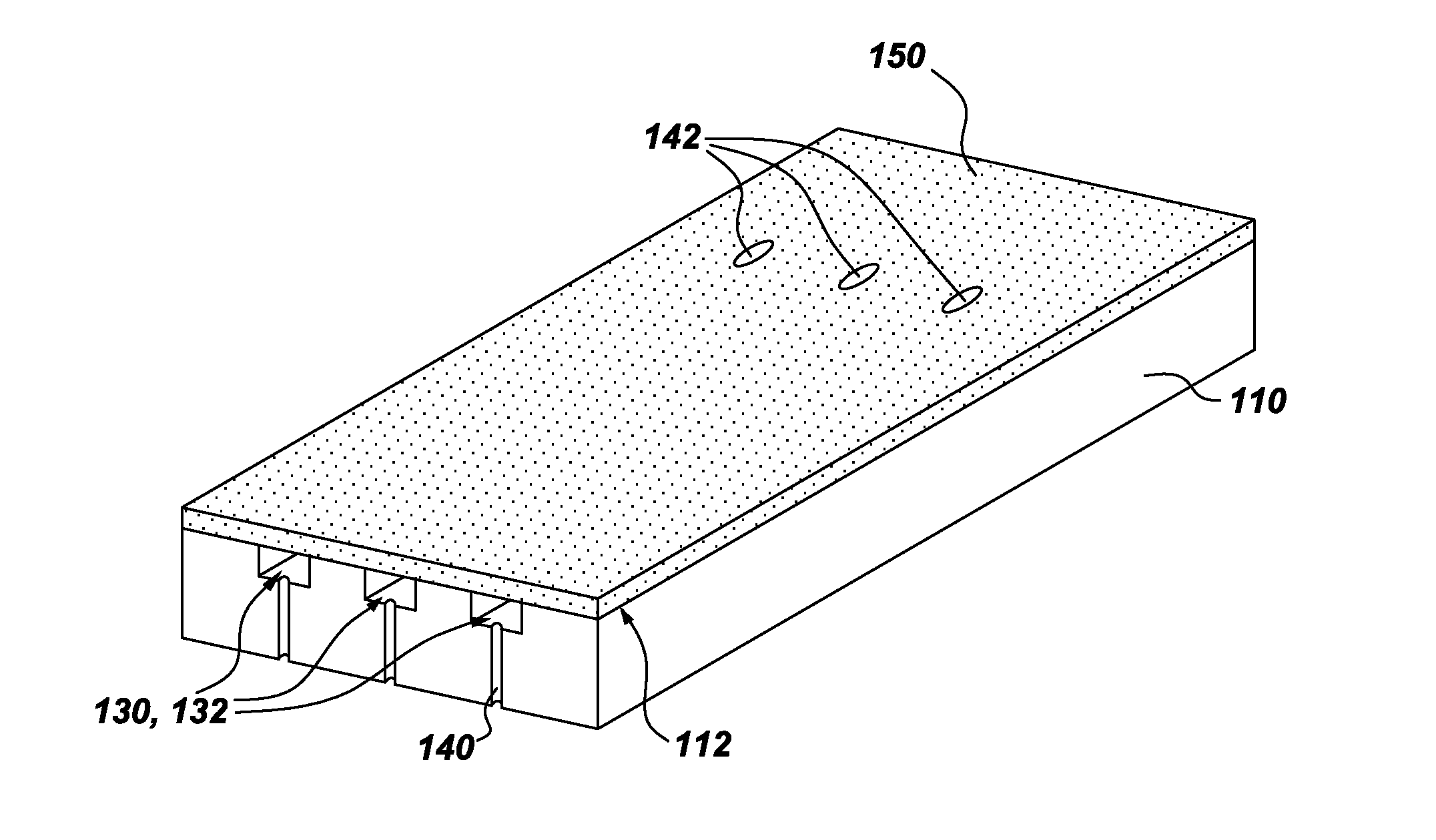
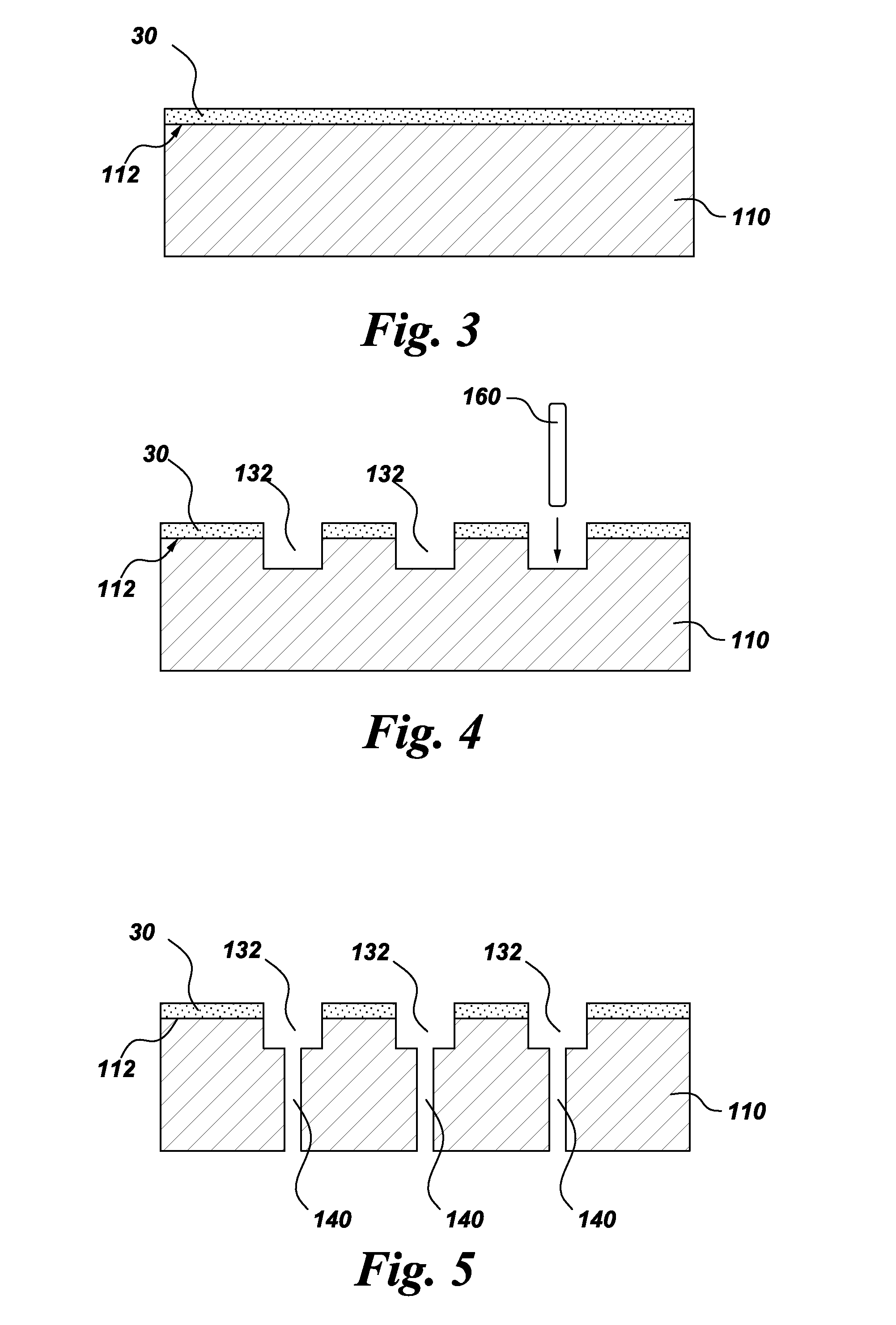
[0050]An example sequence of process steps is as follows. However, this is an example and is not intended to limit the invention. A fugitive coating comprising a Speedmask 729® UV / Visible light curable masking resin was applied to the surface of a single crystal superalloy (Renee N5) substrate. Grooves were formed in the substrate through the fugitive coating using an abrasive water jet. A filler material comprising copper ink was applied as a slurry over the entire surface of the fugitive coated substrate and inside the grooves. The excess filler was wiped off, and the remaining filler was then cured. The maskant (fugitive coating) was removed by performing a heat treatment at 500 degrees Celsius without harming the filler in the channels, but removing any excess filler on the maskant. The remaining cured filler in the channels was then smoothed off flush by grinding the surface. The final metallic bond coat and YSZ (Yttria-stabilised zirconia) thermal barrier coatings were applied...


PUM

PropertyMeasurementUnit
Thicknessaaaaaaaaaa
Abrasiveaaaaaaaaaa

Abstract

A method of fabricating a component is provided. The method includes depositing a fugitive coating on a surface of a substrate, where the substrate has at least one hollow interior space. The method further includes machining the substrate through the fugitive coating to form one or more grooves in the surface of the substrate. Each of the one or more grooves has a base and extends at least partially along the surface of the substrate. The method further includes forming one or more access holes through the base of a respective one of the one or more grooves to connect the respective groove in fluid communication with the respective hollow interior space. The method further includes filling the one or more grooves with a filler, removing the fugitive coating, disposing a coating over at least a portion of the surface of the substrate, and removing the filler from the one or more grooves, such that the one or more grooves and the coating together define a number of channels for cooling the component.

Description

BACKGROUND[0001]The invention relates generally to gas turbine engines, and, more specifically, to micro-channel cooling therein.[0002]In a gas turbine engine, air is pressurized in a compressor and mixed with fuel in a combustor for generating hot combustion gases. Energy is extracted from the gases in a high pressure turbine (HPT), which powers the compressor, and in a low pressure turbine (LPT), which powers a fan in a turbofan aircraft engine application, or powers an external shaft for marine and industrial applications.[0003]Engine efficiency increases with temperature of combustion gases. However, the combustion gases heat the various components along their flowpath, which in turn requires cooling thereof to achieve a long engine lifetime. Typically, the hot gas path components are cooled by bleeding air from the compressor. This cooling process reduces engine efficiency, as the bled air is not used in the combustion process.[0004]Gas turbine engine cooling art is mature and ...

Claims


Application Information

Patent Timeline
IPC IPC(8): B05D5/00B05D3/02B05D3/00B05D1/18C25F3/00B05D1/00C23C16/44C23C16/50C23C4/12B05D3/12B05D1/04
CPCB23P15/04B23P2700/13F01D5/187F01D5/288F05D2230/10F05D2230/31F23R2900/03041F05D2260/204Y02T50/67Y02T50/672Y02T50/676F23M5/08F05D2260/202Y02T50/60
Inventor BUNKER, RONALD SCOTTWEI, BINLIPKIN, DON MARKREBAK, RAUL BASILIO
Owner GENERAL ELECTRIC CO
Why Eureka
Try Eureka