Parallel Robot

a parallel robot and kinematic technology, applied in the field of parallel robots, can solve the problems of large torque transfer, wear of the supply line guided in the elongated hollow body, and the low degree of wear of the supply line, so as to avoid damage to the supply line and ensure the cleaning of all components.

Active Publication Date: 2012-05-17
MAJATRONIC
View PDF17 Cites 46 Cited by
  • Summary
  • Abstract
  • Description
  • Claims
  • Application Information

AI Technical Summary

Benefits of technology

[0007]The object of the invention is to provide an industrial robot with parallel kinematics, which renders possible a reliable cleaning of all components, in which damage to the supply lines is avoided and in which no special demands are made on the material of the supply lines.
[0009]The elongated hollow body can have as components, for example, at least two tubes that can be displaced within one another in a telescoping manner. These are supported inside one another secured against twisting. For this purpose, the tubes can have a circular cross section. An inner tube is thereby equipped with bosses projecting outwards, while the outer tube has grooves that are adapted to the bosses. Bosses and grooves run in the longitudinal direction of the tubes. Furthermore, the tubes can also have a cross section that deviates from a circular shape, for example, an oval or angular cross section. The elongated hollow body comprising at least two tubes arranged inside one another in a telescoping manner has the advantage that it is variable in its length and adapts to the variable distance between the robot base and the carrier element. The distance between the robot base and the carrier element changes with a movement of the actuating units. Furthermore, large torques can be transferred even by tubes with a low weight. However, there is also the possibility of using flexible drive shafts as elongated hollow bodies. These are likewise embodied as hollow bodies and can thus accommodate the supply lines. Furthermore, the elongated hollow body can have only one rigid tube. In order to take into account the variable distance between the robot base and the carrier element, the tube can be displaceably supported on the robot base.
[0025]According to a further advantageous embodiment of the invention, at least one pneumatic or hydraulic control element is arranged in the elongated hollow body for actuating a gripper or tool arranged on the carrier element. A control element of this type comprises one or more valves, for example. Due to the position in the elongated hollow body, the control element is located closer to a gripper or tool than with a positioning of the control element on the robot base. The closer the pneumatic or hydraulic control is arranged to the gripper or the tool, the shorter the distance the compressed air or a pressure liquid has to cover to move the gripper or the tool from the control to the gripper or to the tool. This leads to short reaction times. The valves of the pneumatic or hydraulic control are triggered by electrical signals, the propagation speed of which is much higher than the speed of compressed air or of a pressure liquid. The elongated hollow body shields the pneumatic or hydraulic control from the outside and serves as a housing. The elongated hollow body thus prevents the pneumatic or hydraulic control from being able to come into contact with the objects to be moved or processed. The control therefore does not need to meet any special requirements regarding hygiene.
[0027]The object is furthermore attained through the industrial robot according to the invention with the features of claim 16. The industrial robot is characterized in that it is equipped with at least one actuating unit embodied in a hollow manner. This actuating unit in the form of a control arm has an upper and a lower arm section with respectively one continuous cavity. Furthermore, the actuating unit is equipped with a joint between the two arm sections, which has a continuous cavity. The joint between the lower arm section and the carrier element likewise has a continuous cavity. The cavities of the arm sections and of the joints thereby adjoin one another and form a continuous channel from the robot base to the carrier element. In these continuous cavities at least one supply line is arranged and guided from the robot base to the carrier element. The supply line is thereby protected from contamination and soiling and on the other hand from damage. The arm sections and the joints of the hollow actuating unit are open at the front faces, but otherwise preferably closed so that contamination and cleaning fluids cannot penetrate into the elongated hollow body from outside and particles such as wear debris from the supply lines cannot penetrate to the outside. The supply lines are thus protected against external influences. Moreover, the objects to be processes are protected from contamination by the supply lines. Furthermore, compared to a guidance of the supply lines along the actuating units, the supply lines guided in the at least one hollow actuating unit are subjected to wear to a much lower extent.

Problems solved by technology

Furthermore, compared to a guidance of the supply lines along the actuating units, the supply lines guided in the elongated hollow body and the hollow joint are subjected to wear to a much lower extent, since even with a deflection of the carrier element from the starting position, they run virtually in a straight line or curved by only a small angle.
Furthermore, large torques can be transferred even by tubes with a low weight.

Method used


Image

  • Parallel Robot
  • Parallel Robot
  • Parallel Robot

Examples


Embodiment Construction

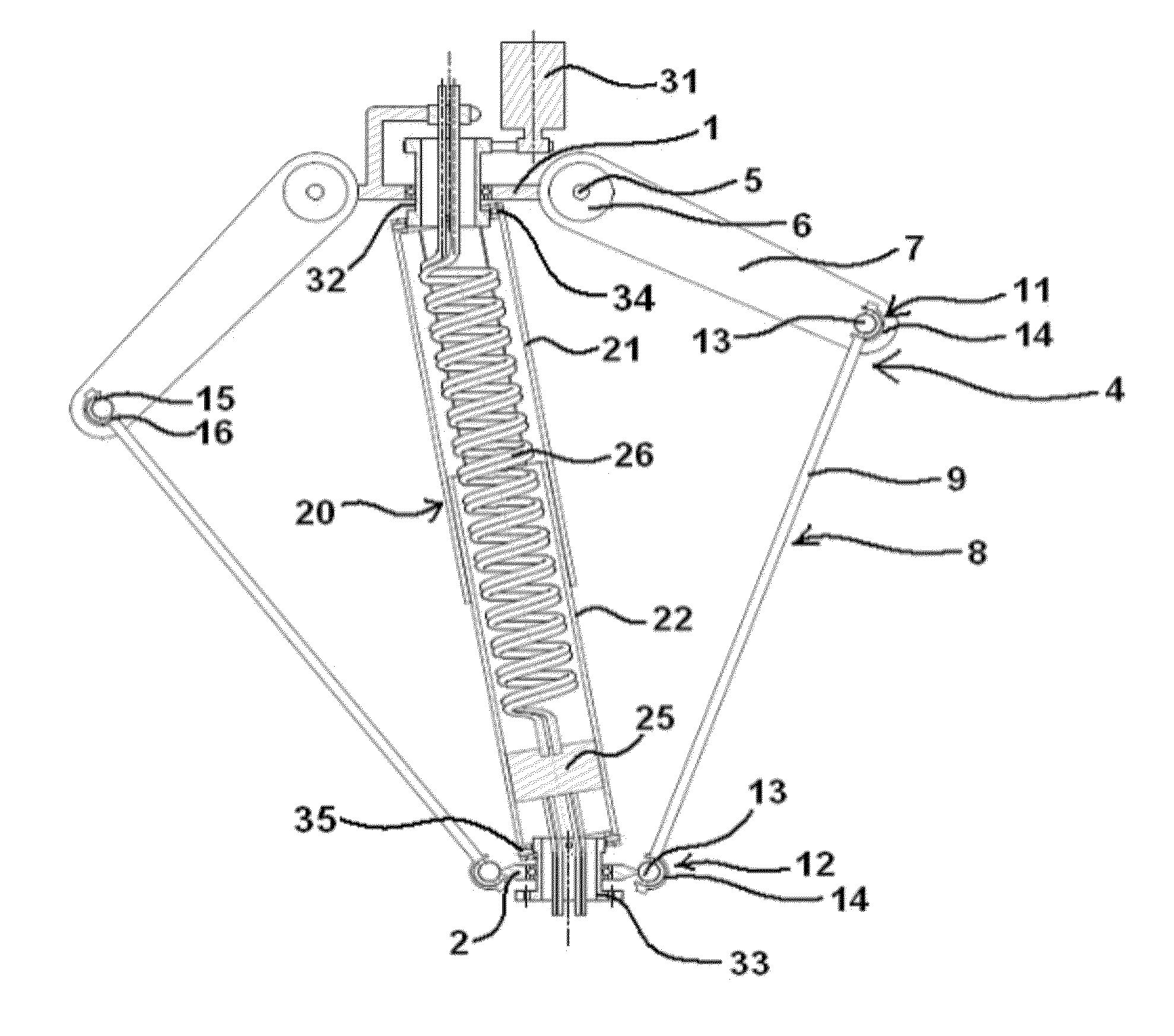
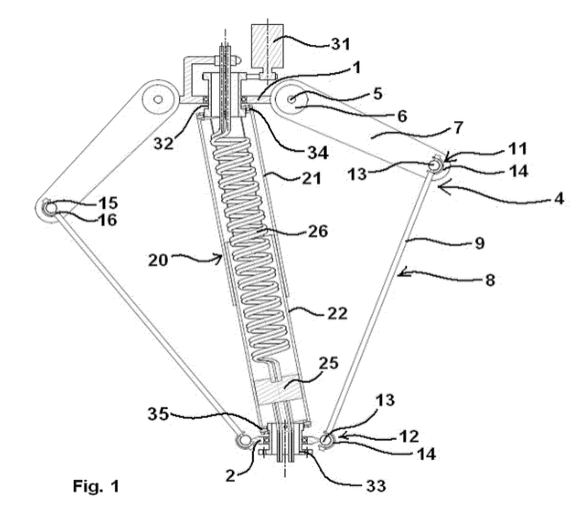
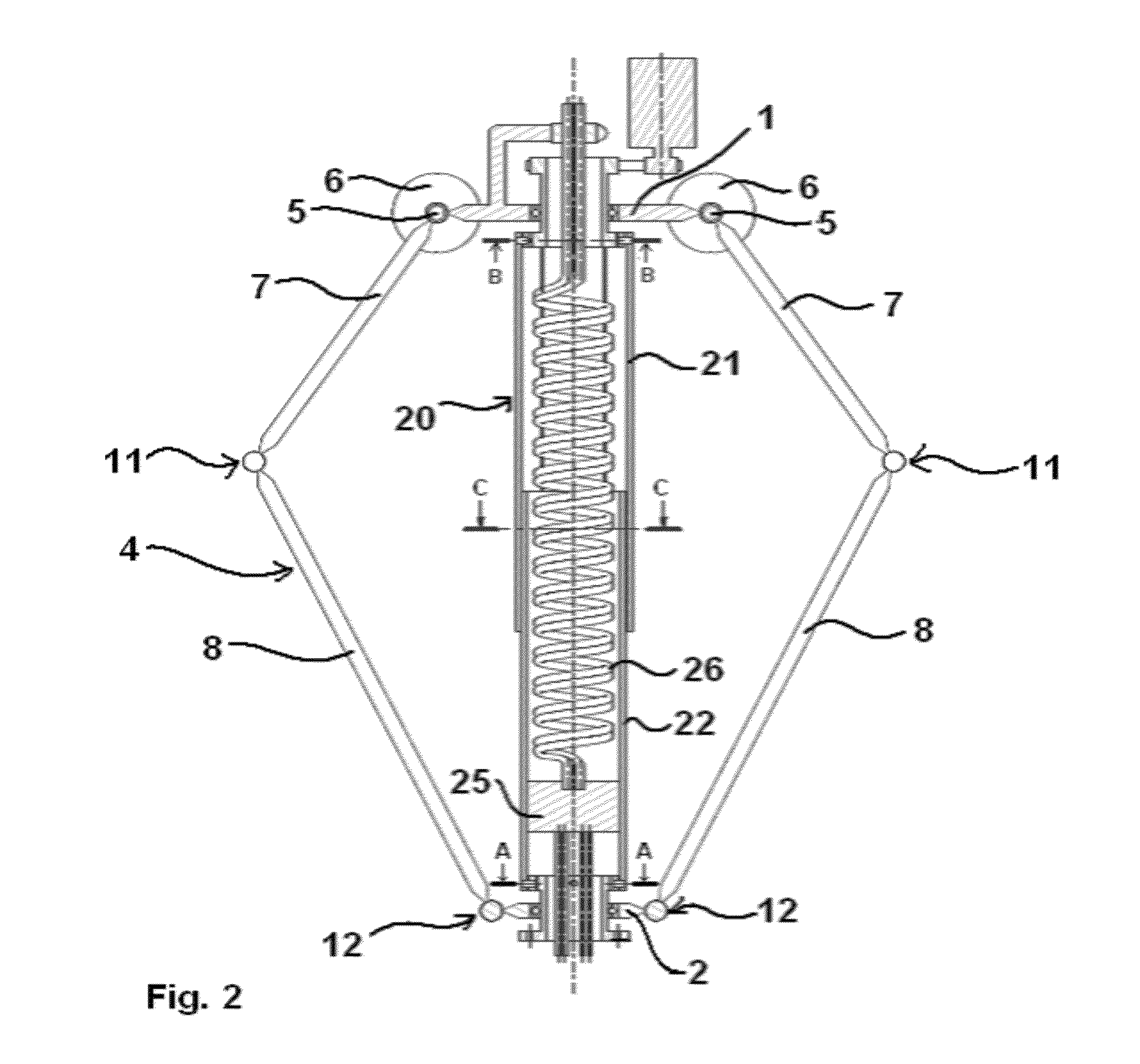
[0047]FIG. 1 shows a first exemplary embodiment of an industrial robot according to the Delta principle with a robot base 1, a carrier element 2, on which a gripper or a tool can be arranged, and two actuating units 4 embodied as control arms. The gripper and the tool are not shown in the drawing. The industrial robot has a total of three actuating units 4 embodied as control arms, but one of the actuating units cannot be seen in the representation. Each of the three actuating units is connected to a motor 6 via a drive shaft 5. The actuating units 4 have an upper arm section 7 and a lower arm section 8. The upper arm section 7 is thereby characterized by high stability and low weight. The lower arm section 8 has two rods 9 and 10 running in a parallel manner. In the drawing in each case only one of the two rods of an actuating unit 4 is discernible. The two rods 9 and 10 of the lower arm section 8 of an actuating unit 4 are connected via joints 11 at their upper end to the upper ar...


PUM


Abstract

The invention relates to an industrial robot having parallel kinematics, the industrial robot, comprising a robot base (1, 38), a carrier element (2, 42) for accommodating a gripper or a tool, several movable, elongated actuating units (4,36), which are connected at one end thereof to drive units (6, 39) arranged on the robot base (1, 38), and the other end of which is movably connected to the carrier element (2, 42), an elongated hollow body (20, 43, 54), which has a continuous cavity and which is flexibly connected to the robot base (1, 38), a joint (35, 49, 65), which has a continuous cavity and which has several degrees of freedom, by means of which joint the elongated hollow body (20, 43, 54) is movably connected to the carrier element (2, 42), and at least one supply line (26, 51, 64) for a gripper arranged on the carrier element (2, 42) or a tool arranged on the carrier element (2, 42), the supply line being guided through the cavity of the elongated hollow body (20, 43, 54) and the cavity of the hollow joint (35, 49, 65) from the robot base to the carrier element (2, 42).

Description

FIELD OF THE INVENTION[0001]The invention is based on an industrial robot with parallel kinematics, which is equipped with a robot base, with a carrier element used as a receptacle for a gripper or a tool and with several actuating units for moving the carrier element.BACKGROUND OF THE INVENTION[0002]Industrial robots of this type with parallel kinematics are used to move, position and / or process an object in space. They include Delta robots, for example. These are equipped with at least two control arms as actuating units. Each control arm has an upper and a lower arm section, which are connected to one another in a moveable manner. Each of the upper arm sections is driven by a drive, for example, a motor-gear unit. The drives are arranged on the robot base. The movement of the upper arm sections is transferred via the lower arm sections to a carrier element. Each lower arm section has two parallel rods or struts running in the longitudinal direction of the arm section, which are m...

Claims


Application Information

Patent Timeline
Patent Type & Authority Applications(United States)
IPC IPC(8): B25J17/00
CPCB25J17/0266Y10T74/20329B25J9/0078B25J19/0029B25J9/0051B25J9/1623
Inventor ILCH, HARTMUT
Owner MAJATRONIC
Why Eureka
Try Eureka