
Hydraulic variable valve lift apparatus

Inactive Publication Date: 2012-05-17
HYUNDAI MOTOR CO LTD
View PDF14 Cites 8 Cited by
  • Summary
  • Abstract
  • Description
  • Claims
  • Application Information

AI Technical Summary

Benefits of technology

[0011]Various aspects of the present invention provide for a hydraulic pressure variable valve lift apparatus having advantages of that is able to adjust a valve lift amount according to the operating condition of an engine and reducing an impact at the moment when the valve is closed such that a valve lift forms a lamp profile
[0013]One side of the first oil passage may be connected to a hydraulic pressure line and a first check valve is disposed at the main oil passage so as to prevent the oil from being flown backward.
[0014]A second oil passage that is diverged from the first oil passage and may be connected to the piston chamber is formed and a second check valve is disposed at the second oil passage so as to prevent the oil from being flown backward. The second oil passage may be connected to a chamber upper end surface of the piston chamber.
[0018]An orifice check valve may be disposed at the orifice hole such that the oil flux that is supplied to the piston chamber through the orifice hole is limited and the supplied oil is prevented from being flown backward.
[0023]A hydraulic pressure variable valve lift apparatus according to various aspects of the present invention reduces an impact at a moment when the valve is closed by having a valve lift formed a ramp profile.
[0024]A hydraulic pressure variable valve lift apparatus according to various aspects of the present invention does not require accurate process of multi orifice and thereby decreases a production cost.

Problems solved by technology

Meanwhile, since a CVVL that is broadly used includes a link, an eccentric cam, a control shaft, and so on and the number of components is large, the inertial weight and the accumulated tolerance become larger and there is a drawback in developing moving characteristics of the CVVL system.
Also, since the valve of the cylinder is simultaneously controlled by the same camshaft, the free valve movement is restricted.

Method used


Image

  • Hydraulic variable valve lift apparatus
  • Hydraulic variable valve lift apparatus
  • Hydraulic variable valve lift apparatus

Examples


Embodiment Construction

[0031]Reference will now be made in detail to various embodiments of the present invention(s), examples of which are illustrated in the accompanying drawings and described below. While the invention(s) will be described in conjunction with exemplary embodiments, it will be understood that present description is not intended to limit the invention(s) to those exemplary embodiments. On the contrary, the invention(s) is / are intended to cover not only the exemplary embodiments, but also various alternatives, modifications, equivalents and other embodiments, which may be included within the spirit and scope of the invention as defined by the appended claims.

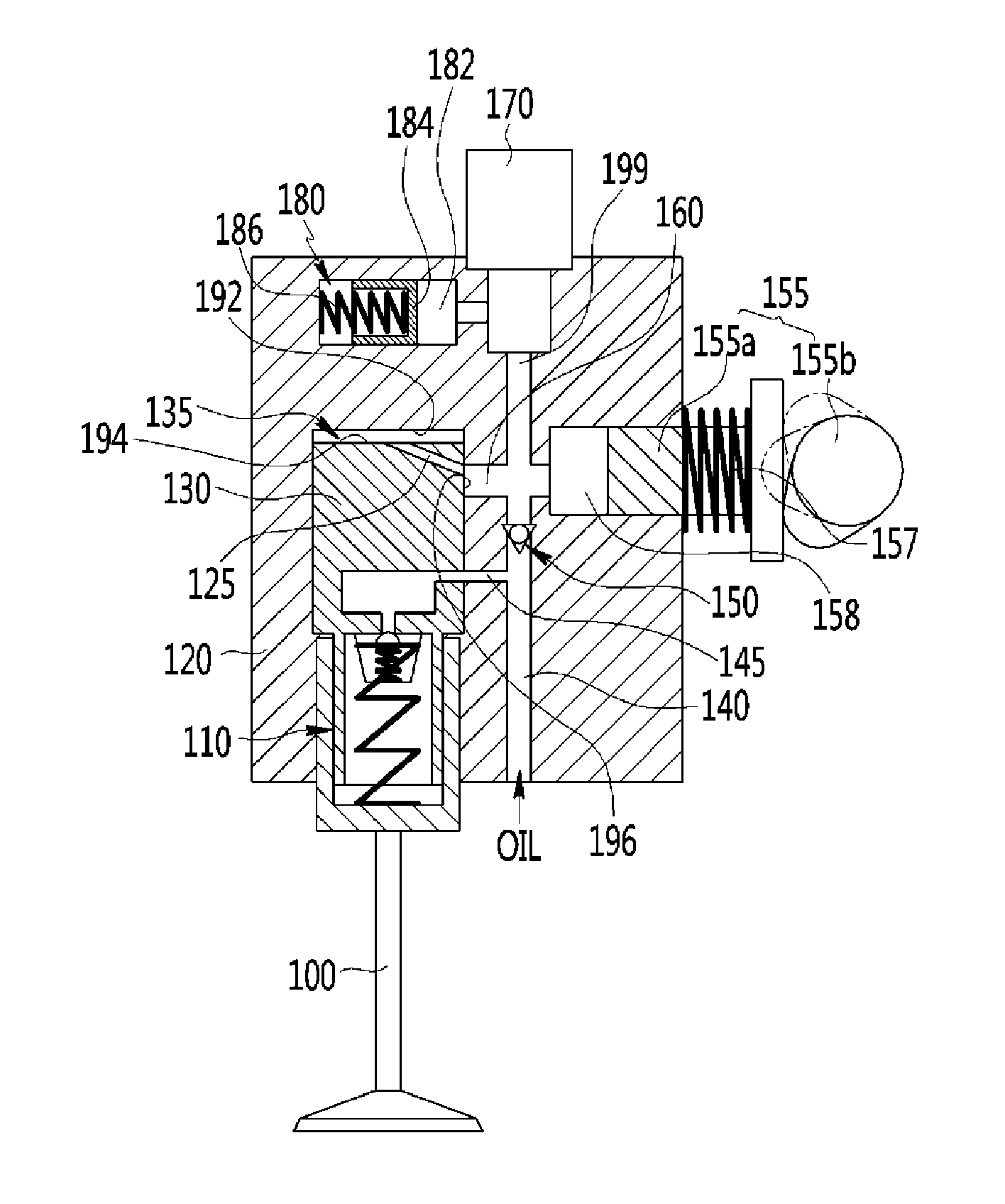
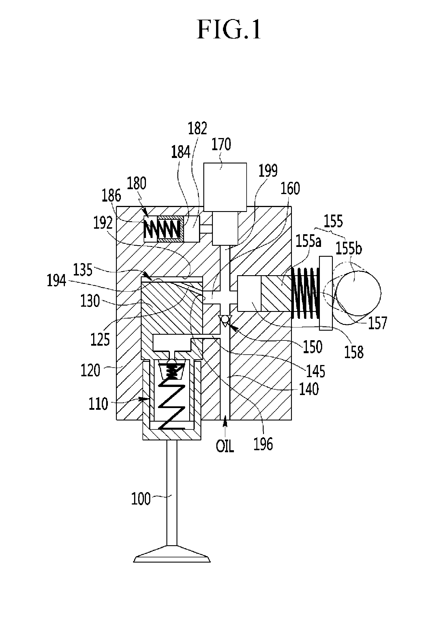
[0032]Referring to FIG. 1, a hydraulic pressure variable valve lift apparatus includes housing.

[0033]A piston chamber 135, which is opened in a lower side, is formed, in the housing 120, a valve operating piston 130 is disposed in the piston chamber 135, a hydraulic pressure gap adjuster 110 (e.g., HLA: hydraulic lash adjuster) is dis...


PUM


Abstract

A hydraulic pressure variable valve lift apparatus may include a housing that a piston chamber that one side thereof is opened is formed, a valve operating piston that is slidably disposed in the piston chamber and one end thereof is connected to a valve for opening / closing a port, and an EHV hydraulic pump that is configured to supply the piston chamber with oil, wherein a first oil passage is formed between the EHV hydraulic pump and the piston chamber on as to supply a side surface of the piston chamber with oil, and an orifice hole is formed from a piston side surface of the valve operating piston to a piston upper end surface. Accordingly, the valve lift amount can be varied according to the operating condition of the engine, a hydraulic pressure variable valve lift apparatus reduces an impact at a moment when the valve is closed by having a valve lift formed a ramp profile and does not require accurate process of multi orifice and thereby decreases a production cost.

Description

CROSS-REFERENCE TO RELATED APPLICATION[0001]This application claims priority to and the benefit of Korean Patent Application No. 10-2010-0112299 filed Nov. 11, 2010, the entire contents of which application is incorporated herein for all purposes by this reference.BACKGROUND OF INVENTION[0002]1. Field of Invention[0003]The present invention relates to a valve lift apparatus. More particularly, the present invention relates to a hydraulic pressure variable valve lift apparatus that varies lift mount of a valve for opening / closing a port of an internal combustion engine.[0004]2. Description of Related Art[0005]An internal combustion engine takes fuel / air into a combustion chamber and combusts them to generate power. An intake valve is opened by a cam shaft to suck in the air and the air is supplied into the combustion chamber while the intake valve is opened.[0006]Also, an exhaust valve is lifted by a camshaft and the combustion gas is exhausted from the combustion chamber while the e...

Claims


Application Information

Patent Timeline
IPC IPC(8): F01L9/02F01L9/11F01L9/14
CPCF01L9/025F01L9/021F01L9/11F01L9/14
Inventor CHOI, BYONG YOUNGKWAK, YOUNG HONGSHIN, GEE WOOKKONG, JIN KOOKWOO, SOO HYUNGKIM, JIN SOON
Owner HYUNDAI MOTOR CO LTD
Features
  • Generate Ideas
  • Intellectual Property
  • Life Sciences
  • Materials
  • Tech Scout
  • Unparalleled Data Quality
  • Higher Quality Content
  • 60% Fewer Hallucinations
Learn More