Induction Cook-Top Apparatus

a technology of induction stove and cook-top, which is applied in the direction of induction heating, electric/magnetic/electromagnetic heating, electrical appliances, etc., can solve the problems of dangerously hot heating element of traditional electric stove, difficult cleaning of gas stove, and inability to heat the cooking vessel itself, etc., to improve the convenience and safety of cooking.

Active Publication Date: 2012-05-17
KENYON INT
View PDF23 Cites 54 Cited by
  • Summary
  • Abstract
  • Description
  • Claims
  • Application Information

AI Technical Summary

Benefits of technology

[0014]In this regard, the present invention provides induction stove assemblies and devices for use w

Problems solved by technology

However, instead of heating a resistive element (such as a coil of metal) by passing electric current through it, an induction stove generates an oscillating magnetic field that causes the cooking vessel itself to be heated.
Gas stoves are often much more difficult to clean because of the need to have deep recesses for the grates on which cooking vessels are placed and protrusions for the gas outlets.
As is well known, the heating element of a traditional electric stove remains dangerously hot for a long period after the stove is turned off.
This residual and unwanted heat poses a clear safety hazard, which can be largely overcome by induction stoves.
Unfortunately, prior art induction stoves, while possessing many advantages over traditional gas and electric stoves, still suffer from notable drawbacks.
Also, very heavy cooking vessels (such as those made from cast iron) may crack or break the cook-top if they are mishandled or dropped on the cook-top.
Additionally, it is sometimes undesirable to clean the cook-top itself.
For example, the cook-top may retain some residual heat from the cooking, or the cook-t

Method used


Image

  • Induction Cook-Top Apparatus
  • Induction Cook-Top Apparatus
  • Induction Cook-Top Apparatus

Examples


Embodiment Construction

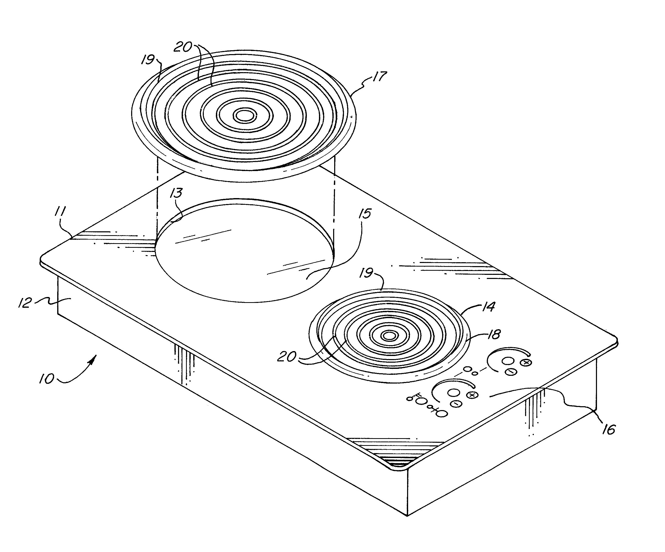
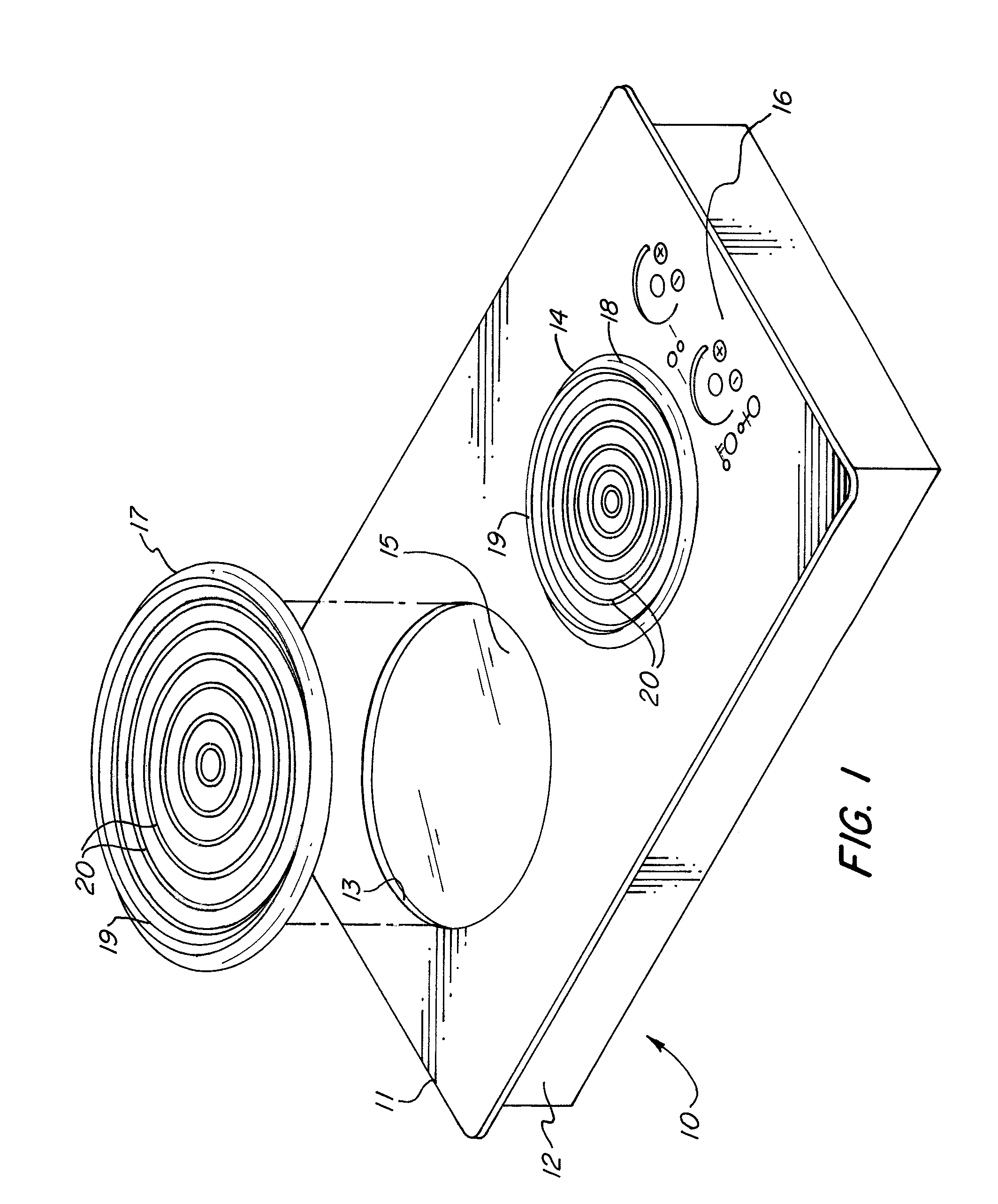
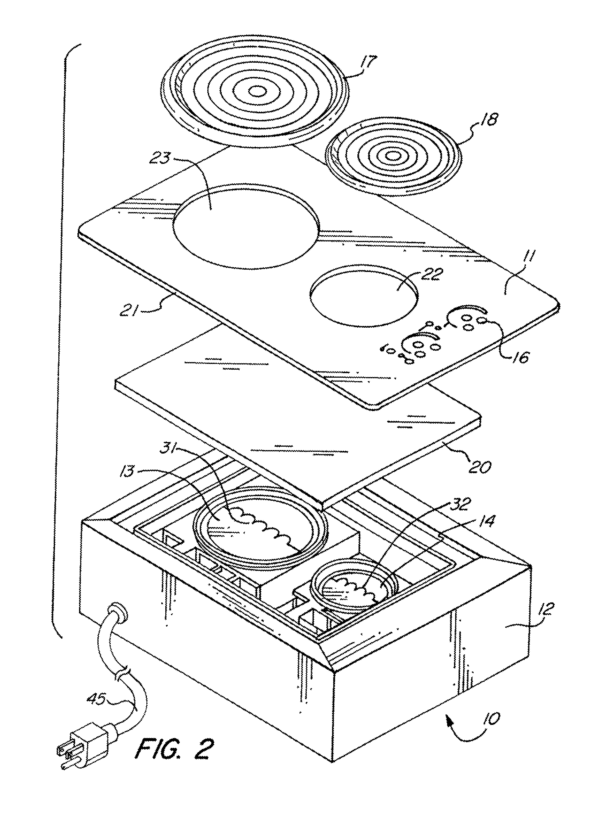
[0044]Referring first to FIG. 1, an induction stove assembly 10 is shown. The assembly 10 includes a cook-top 11 that rests on and is secured to a cabinet 12. The assembly 10 includes two induction cooking zones 13 and 14 which are controlled by the controls 16. Controls 16 include power buttons and temperature selection buttons for each cooking zone. A locking button is also included, which can be used to prevent unwanted use of the assembly 10 by a child.

[0045]The induction cooking zones have different sizes—zone 13 is a larger cooking zone than zone 14. The zone 13 has a larger horizontal extent than the zone 14. A larger induction cooking zone is able to heat a large cooking vessel quicker and more evenly than a smaller induction cooking zone would heat that same vessel. Each induction cooking zone has associated with it a recess formed in the cook-top 11. In FIG. 1, only recess 15 corresponding to the induction cooking zone 13 is visible, but the recess corresponding to zone 14...


PUM


Abstract

An induction stove assembly that utilizes pads between the cook-top of the stove and cooking vessels placed on the stove for heating. The pads are easily removable and interchangeable with other similar pads. The pads help protect the cook-top from damage, make clean-up more efficient, and insulate the cook-top from excessive heating.

Description

CROSS-REFERENCE TO RELATED APPLICATIONS[0001]This application is a continuation-in-part of copending U.S. patent application Ser. No. 12 / 468,591, filed on May 19, 2009, which claims the benefit under 35 U.S.C. §119 (e) of U.S. Provisional Application No. 61 / 080,858,filed on Jul. 15, 2008 and U.S. Provisional Application No. 61 / 054,693, filed on May 20, 2008. The content of all prior applications is incorporated herein by reference.FIELD OF THE INVENTION[0002]The present invention relates to induction stoves. More particularly, the present invention relates to induction stove assemblies having improved safety and convenience and devices for improving the safety and convenience of an induction stove.BACKGROUND OF THE INVENTION[0003]Induction stoves have been known for decades but have gained popularity in recent years due to their many advantages over other types of stoves. Like a traditional electric stove, an induction stove uses electricity to generate heat. However, instead of hea...

Claims


Application Information

Patent Timeline
IPC IPC(8): H05B6/12
CPCH05B6/1209
Inventor WILLIAMS, PHILLIPREISCHMANN, MICHAEL
Owner KENYON INT
Why Eureka
Try Eureka