Respiratory induction apparatus, respiratory induction program, and particle beam therapy system

a technology of induction apparatus and respiratory induction program, which is applied in the field of respiratory induction apparatus, respiratory induction program, and particle beam therapy system, can solve the problems of inability to accurately evaluate respiration, inability to implement appropriate control or instruction, and inability to achieve optimum timing for irradiation

Active Publication Date: 2012-05-17
MITSUBISHI ELECTRIC CORP
View PDF2 Cites 29 Cited by
  • Summary
  • Abstract
  • Description
  • Claims
  • Application Information

AI Technical Summary

Benefits of technology

[0015]In a respiratory induction apparatus and a particle beam therapy system according to the present invention, respiration is evaluated based on the gain and the phase calculated by use of a pair of coefficients, of trigonometric functions, corresponding to 1st-order terms by means of Fourier series expansion of respective signal data pieces acquir...

Problems solved by technology

Therefore, for example, in the case where respiration is irregular or in the case where noise is superimposed on the respiratory waveform, i.e., in the case where an unanticipated waveform is caused,...

Method used


Image

  • Respiratory induction apparatus, respiratory induction program, and particle beam therapy system
  • Respiratory induction apparatus, respiratory induction program, and particle beam therapy system
  • Respiratory induction apparatus, respiratory induction program, and particle beam therapy system

Examples


embodiment 1

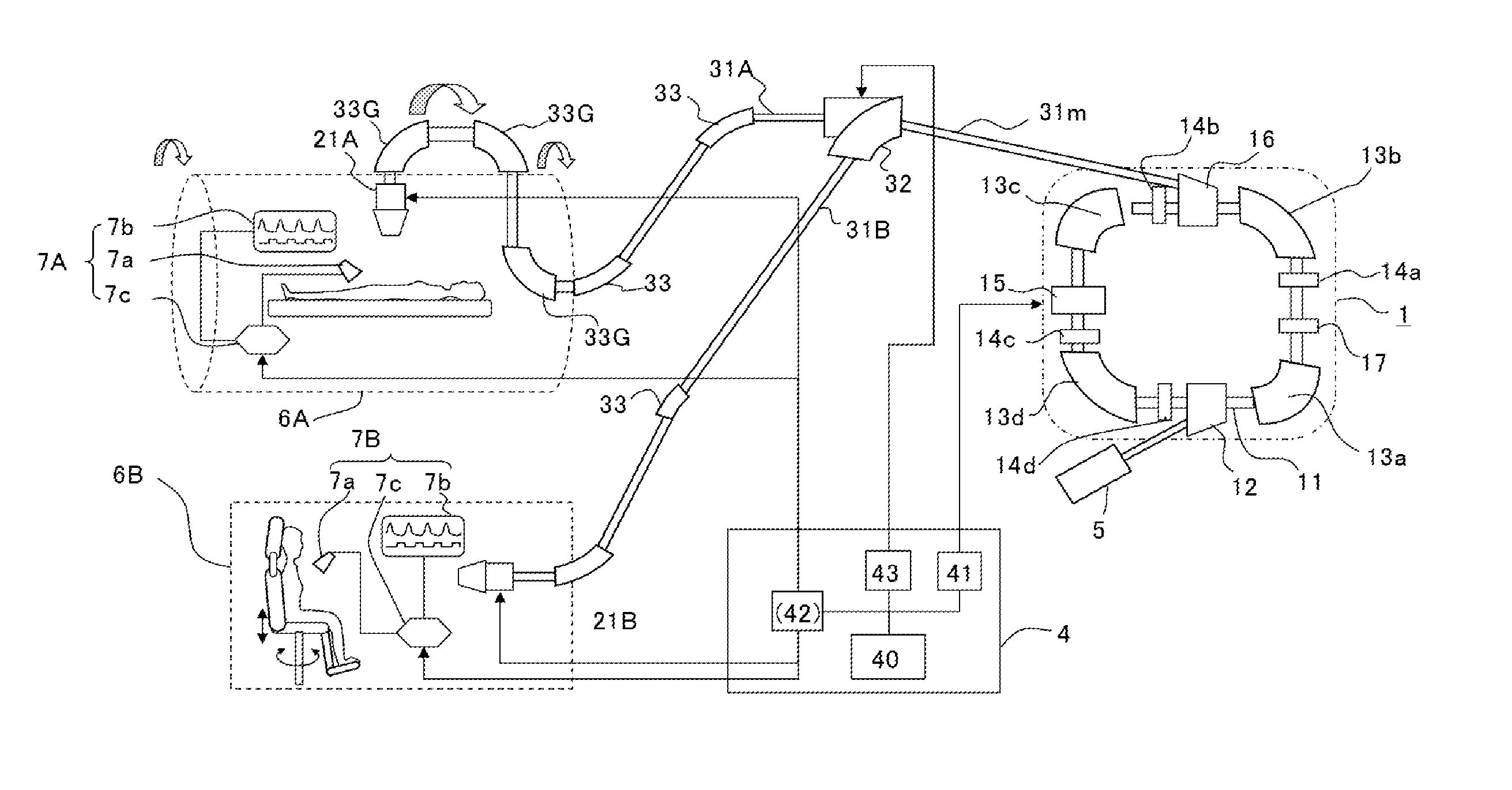
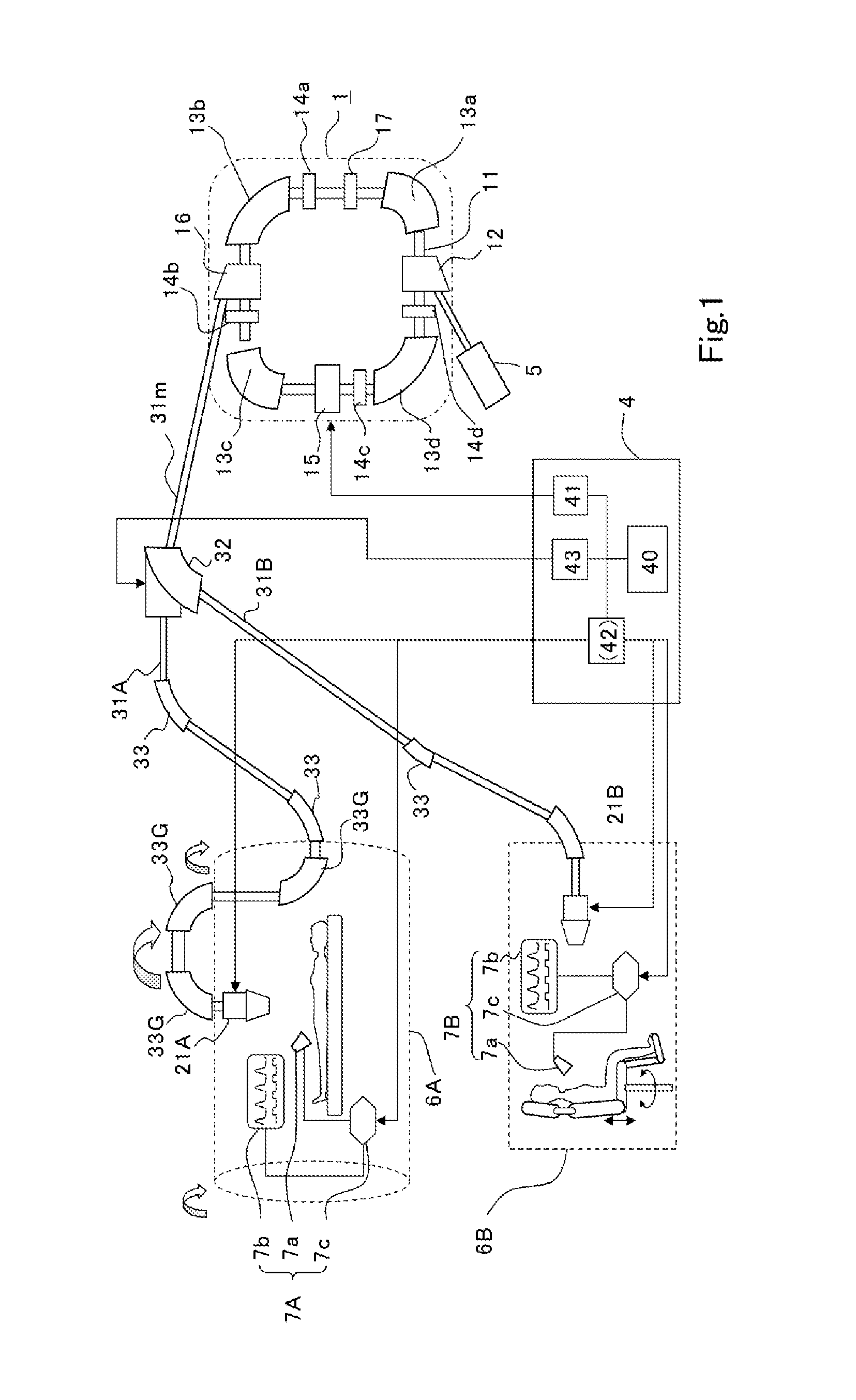
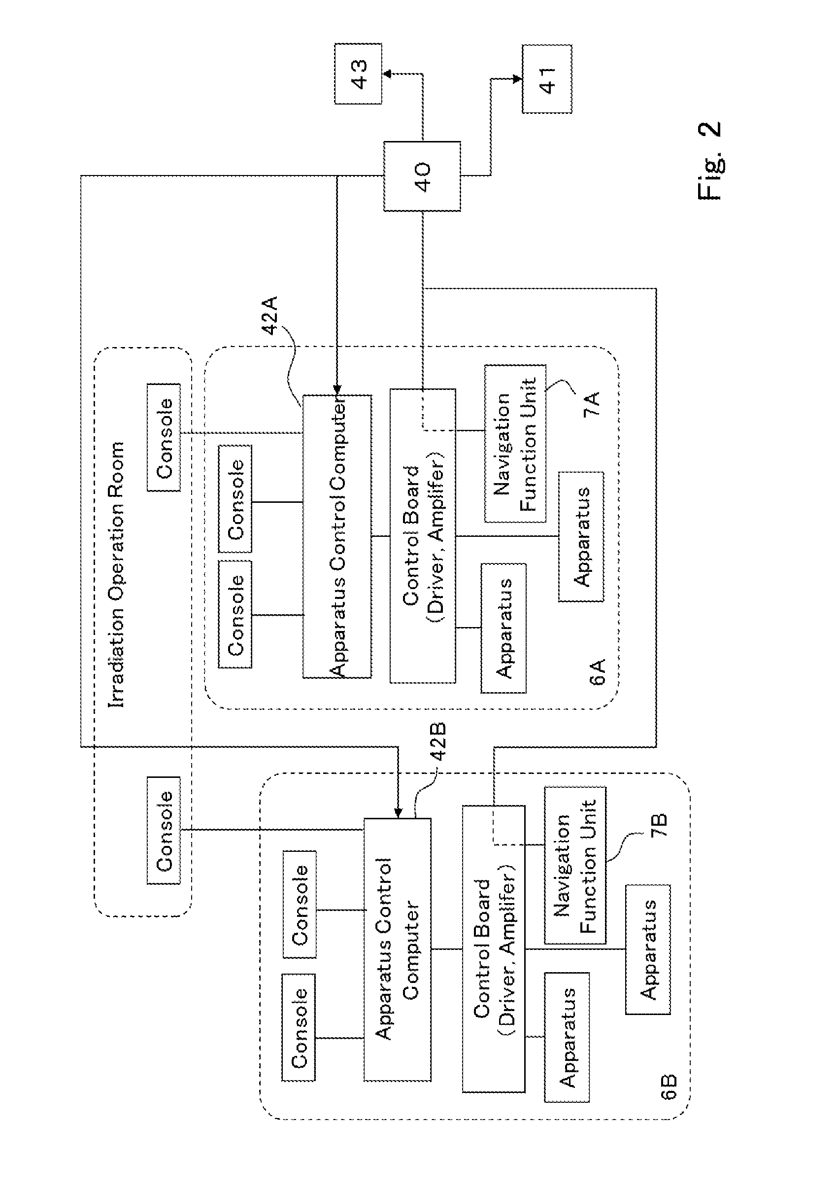
[0029]The configuration of a respiratory induction apparatus (respiratory navigation apparatus) according to Embodiment 1 of the present invention and the configuration of a particle beam therapy system provided with the respiratory induction apparatus will be explained below. FIGS. 1 through 7 are to explain the configurations of a respiratory induction apparatus and a particle beam therapy system according to Embodiment 1 of the present invention; FIG. 1 is a diagram illustrating the whole configuration of a particle beam therapy system; FIG. 2 is a functional block diagram for explaining the configuration related to control of a particle beam therapy system; FIG. 3 is a waveform chart representing the relationship among a (desired) respiratory signal, an evaluation function, and a respiration gate signal; FIG. 4 is a complex plane graph representing the relationship among the gain and the phase when a respiratory signal is evaluated by utilizing an evaluation function; FIG. 5 is ...

embodiment 2

[0097]It goes without saying that in the respiratory induction apparatus 7 according to Embodiment 1, the respective portions, represented in the block diagram of FIG. 6, for performing, for example, the operation represented in FIG. 8 can be configured by use of dedicated hardware. However, it can be understood that the functions of the portions, in the respiratory induction apparatus 7, other than the respiration synchronization sensor 7a among the portions illustrated in FIG. 6 can be realized by a universal computer or a workstation. That is to say, in the case where it is assumed that a universal computer or a workstation is utilized, most of the functions in respiratory navigation can readily be realized by use of a program that works on the computer or the like. Accordingly, in Embodiment 2, there will be explained a program for realizing a respiratory induction apparatus on a computer. In Embodiment 2, this program is referred to as a “respiratory induction program according...

embodiment 3

[0106]In Embodiment 3 of the present invention, in the quantitative evaluation of respiration, there is implemented a comprehensive evaluation in addition to the evaluation of the gain and the phase, described in Embodiments 1 and 2. The method in which real respiration is most directly evaluated is a method of evaluating the error between the real respiratory signal Rrl(t) and the desired respiratory signal Rtj(t) as represented in the equation (5).

Jres:=∫02π(Rrl(t)−Rtj(t))2dωrest  (5)

where Jres is an evaluation function.

[0107]In the equation (5), the evaluation function Jres is given as a function of continuous time; however, as explained in the “calculation performed every sampling period” of Embodiment 1, Jres is discretely calculated in practice. As is the case with the equation (2), the integration range of the equation (5) for calculating the evaluation function Jres is a single respiration period Tres. Accordingly, as is the case with the equation (2), it is conceivable that...


PUM


Abstract

The objective is to obtain a respiratory induction apparatus and a particle beam therapy system in which respiration can appropriately be induced by accurately evaluating the respiration. There are provided a respiratory induction control unit (7cC) that generates a desired respiratory signal (Rtj(t)) for respiratory induction; a real respiration measurement unit (7a) that outputs a real respiratory signal (Rrl(t)) obtained by measuring real respiration of a patient; and a respiration evaluation unit (7cE) in which by, as a unit, utilizing data of a single period (Tres) of the desired respiratory signal (Rtj(t)), there is calculated a pair of coefficients (a1 and b1), of trigonometric functions, which correspond to the 1st-order terms by means of Fourier series expansion of data of the desired respiratory signal (Rtj(t)) and data of the real respiratory signal (Rrl(t)), which is acquired in synchronization with the data of the desired respiratory signal (Rtj(t)), and there are performed comparisons between the respective gains (Gtj and Grl) and between the respective phases (φtj and φrl), which are obtained from the coefficients (a1 and b1), so that there is evaluated a misalignment of the real respiration from the desired respiratory signal.

Description

TECHNICAL FIELD[0001]The present invention relates to a particle beam therapy system, which is a medical system that performs therapy by irradiating a charged particle beam, including a heavy ion particle beam such as a carbon ion beam or a proton beam, onto the diseased site of a cancer or the like; the present invention relates particularly to a respiratory induction apparatus that induces the respiration of a patient.BACKGROUND ART[0002]In the particle beam therapy, therapy is implemented by irradiating a charged particle beam (referred to as a particle beam, hereinafter) onto a diseased site, which is a therapy subject, so as to cause damage to diseased tissue; it is required to give a sufficient dose to the diseased tissue, which is an irradiation subject, and suppress a dose to the peripheral tissues. Accordingly, there is generated a treatment plan in order to control the irradiation dose and the irradiation coverage (referred to as an irradiation field, hereinafter) in accor...

Claims


Application Information

Patent Timeline
IPC IPC(8): A61B5/08G21K5/00
CPCA61B5/08G21K5/00A61N2005/1087A61N5/1048A61N5/1068A61B6/541A61N5/1079
Inventor IWATA, TAKAAKI
Owner MITSUBISHI ELECTRIC CORP
Why Eureka
Try Eureka