

Capacitive load drive circuit, liquid injector, and medical device
- Summary
- Abstract
- Description
- Claims
- Application Information
AI Technical Summary
Benefits of technology
Problems solved by technology
Method used
Image

Examples
first modified example
D-1. First Modified Example
[0056]In the above described embodiment, the modulator 230 has been explained to perform pulse modulation of the dWCOM using a method of the so-called pulse width modulation (PWM). However, the method of pulse modulation is not limited to the pulse width modulation, but pulse modulation maybe performed using a method of the so-called pulse density modulation (PDM). As below, the first modified example of modulation using the method called pulse density modulation will be explained.
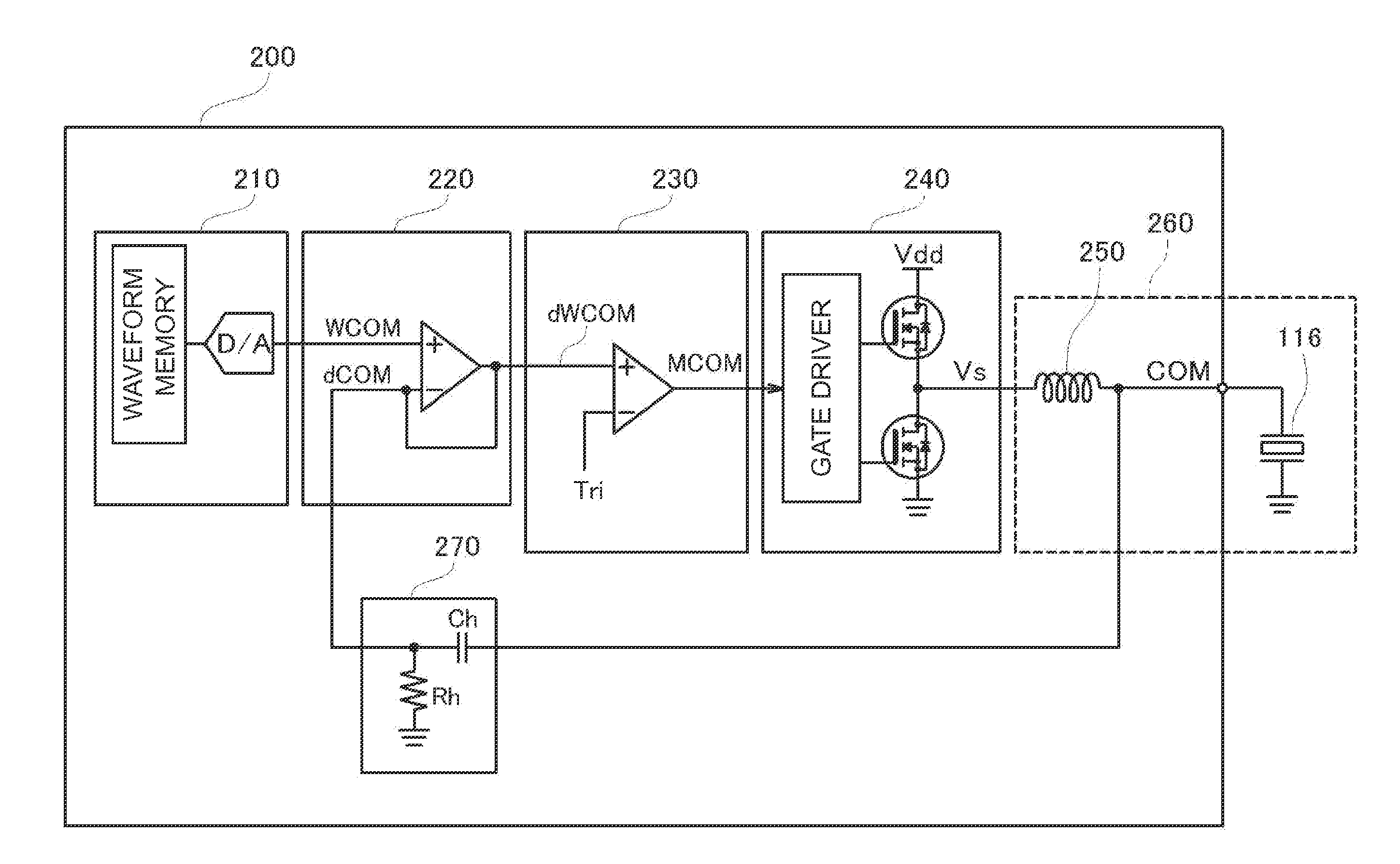
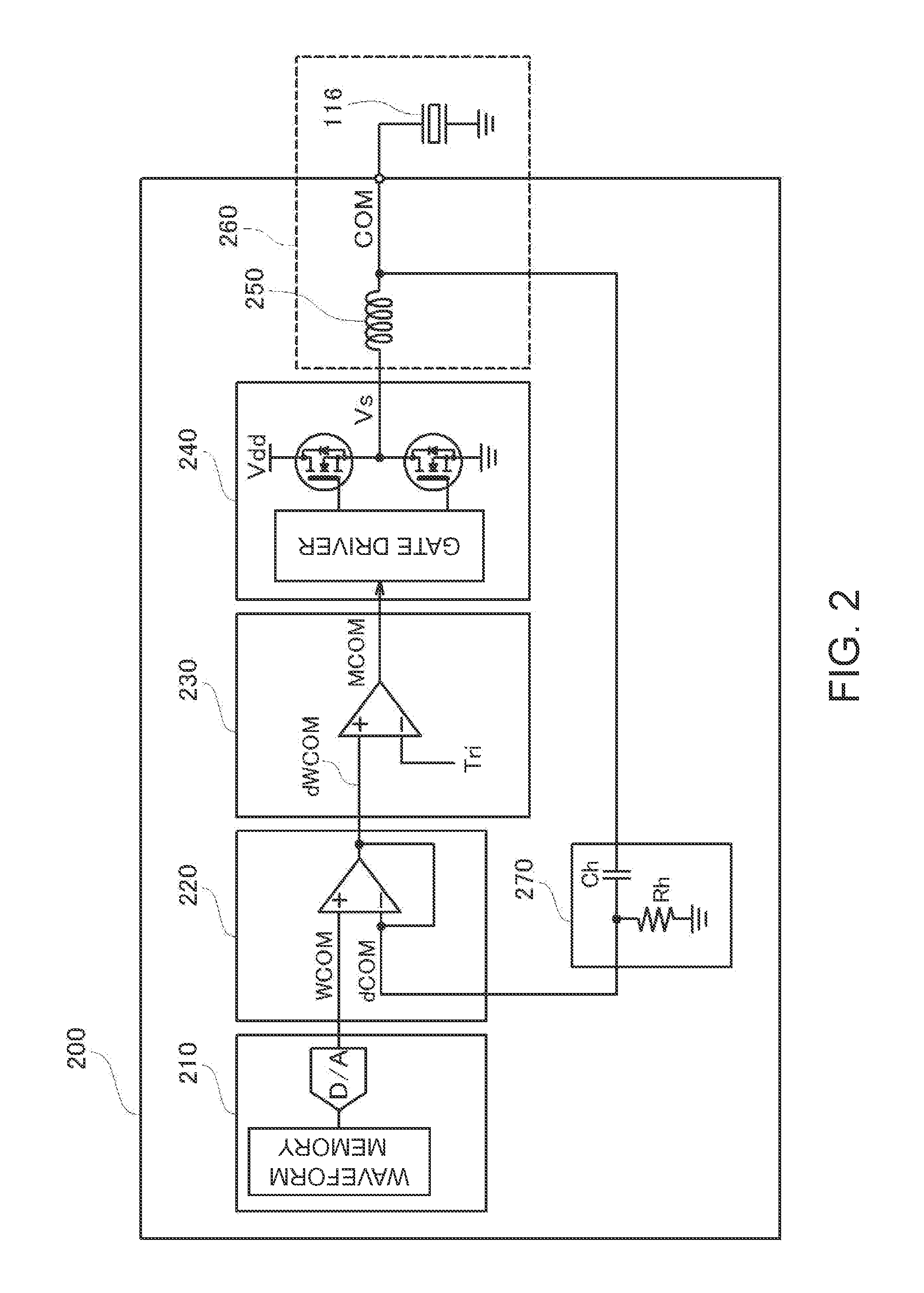
[0057]FIG. 6 is an explanatory diagram showing circuit configurations of a modulator 235 and a digital power amplifier circuit 240 used in a capacitive load drive circuit 200 of the first modified example. The modulator 235 of the first modified example includes an integrator 236 that integrates the difference between a dWCOM (error signal) and a signal obtained by voltage division of the Vs (amplified digital signal) from the digital power amplifier 240 using a resistor Rs and a...
PUM
 Abstract
Description
Claims
Application Information