Phase-Locked Loop

a phase-locked loop and loop technology, applied in the direction of electrical equipment, pulse automatic control, etc., can solve the problems of excessive surge energy, impose interference on oscillation signals, and prolong the locking speed of the pll b, so as to reduce the time needed for locking the pll, the effect of preventing damping

Active Publication Date: 2012-05-17
MEDIATEK INC
View PDF9 Cites 39 Cited by
  • Summary
  • Abstract
  • Description
  • Claims
  • Application Information

AI Technical Summary

Benefits of technology

[0008]The invention is directed to a novel PLL structure, in which a digital charging path is utilized to replace the analog charging path consisted of a second charge pump 22B and a capacitor C2 in the prior art. The digital charging path can be designed to directly provide a predetermined charge amount according to a phase difference, so as to steadily pull up a reference voltage provided to an active filter to prevent damping and effectively reduce time needed for locking the PLL.

Problems solved by technology

However, the existence of the cyclic pulses imposes interference on oscillation signals at the output of the VCO 14.
A shortcoming of the type-I PLL is that the charging pulses usually result in excessively high surge energy.
Further, the damping process also lengthens the locking speed of the PLL 20.

Method used


Image

  • Phase-Locked Loop
  • Phase-Locked Loop
  • Phase-Locked Loop

Examples


first embodiment

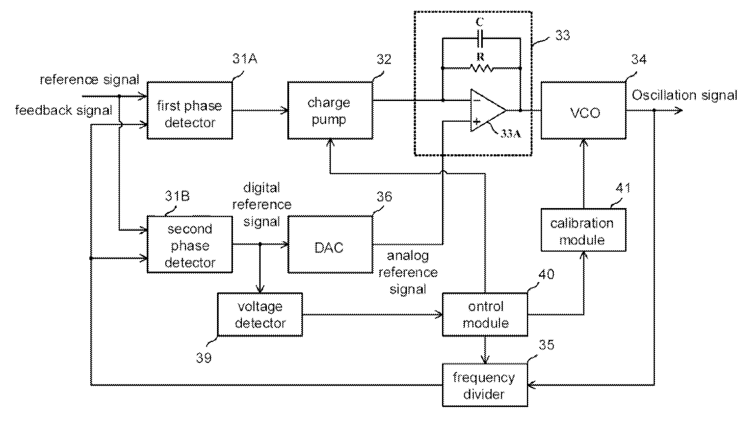
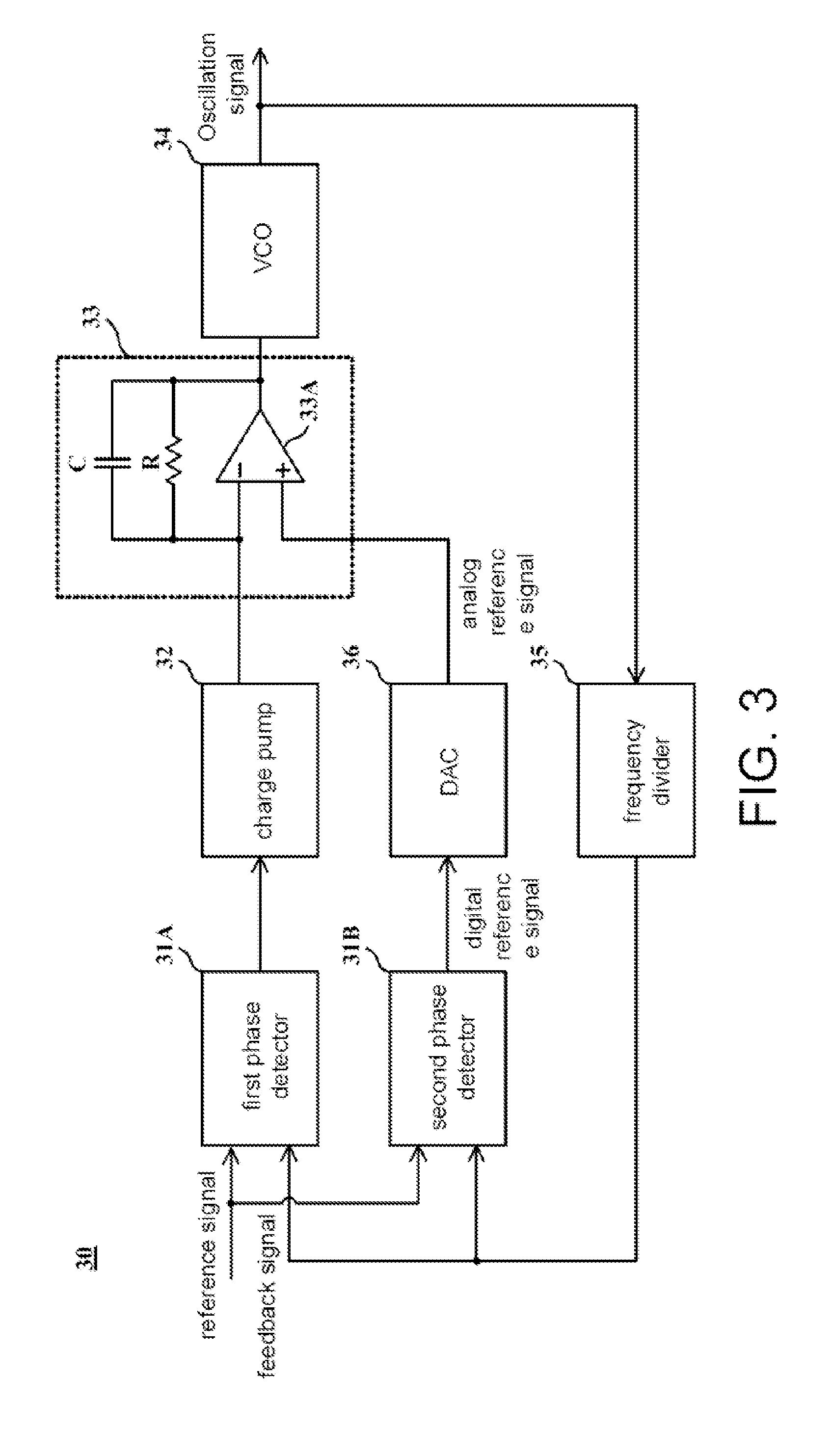
[0019]FIG. 3 shows a schematic diagram of a PLL according to the present invention. A PLL 30 comprises two phase detectors 31A and 31B, a charge pump 32, an active filter 33 consisted of a resistor R, a capacitor C and an operational amplifier 33A, a VCO 34, a frequency divider 35, and a DAC 36.

[0020]As shown in FIG. 3, the active filter 33 comprises a first input connected to the charge pump 32, a second input connected to the DAC 36, and an output for providing a control signal. The capacitor C and the resistor R are connected in parallel between the first input and the output. The VCO 34 generates an oscillation signal according to the control signal. The frequency divider 35 frequency divides the oscillation signal to generate a feedback signal. In the other words, the feedback signal associating with the oscillation signal. According to a reference signal inputted to the PLL 30 and the feedback signal, the first phase detector 31A generates a phase difference signal. The charge...

third embodiment

[0027]A PLL having a calibration function is disclosed according to the present invention. With reference to FIG. 6A, apart from the elements shown in FIG. 3, the PLL according to this embodiment further comprises a voltage detector 39, a control module 40 and a calibration module 41. In this embodiment, the charge pump 32 is designed as being capable of selectively providing a predetermined current Inorm or a test current Itest, and the frequency divider 35 is designed as being capable of selectively providing a predetermined frequency dividing amount Nnorm or a predetermined test frequency dividing amount Ntest. For example, the predetermined current Inorm and the predetermined frequency dividing amount Nnorm are a current amount and a frequency dividing amount provided to the PLL during normal operations.

[0028]When the predetermined current amount Inorm and the predetermined frequency dividing amount Nnorm are provided, a loop gain Gloop of the PLL is represented as:

Gloop=Inorm×R...

fifth embodiment

[0044]A calibration method for a PLL is provided according to the present invention. The PLL comprises a charge pump and a frequency divider. The calibration method comprises steps shown in FIG. 7. In Step S71, a predetermined current amount Inorm is provided at the charge pump, and a predetermined frequency dividing a Nnorm is provided at the frequency divider. In Step S72, when the PLL is locked, a voltage associated with an output frequency of the PLL is measured to generate a first reference voltage V1. In Step S73, a test current amount Itest is provided at the charge pump, and the predetermined frequency dividing amount Nnorm is provided at the frequency divider. In Step S74, when the PLL is locked, the voltage is again measured to generate a second reference voltage V2.

[0045]In Step S75, the predetermined current amount Inorm provided at the charge pump, and a test frequency dividing amount Ntest is provided at the frequency divider, wherein the test frequency dividing amount...


PUM


Abstract

A phase-locked loop (PLL) including an active filter, a voltage-controlled oscillator (VCO), two phase detectors, a charge pump and a digital-to-analog converter (DAC) is provided. The VCO generates an oscillation signal according to a control signal provided at an output of the active filter. The first phase detector generates a phase difference signal according to a reference signal and a feedback signal associating with the oscillation signal. The charge pump provides a charging current to a first input of the active filter according to the phase difference. The second phase detector generates a digital reference signal according to the phase difference between the reference signal and the feedback signal. The DAC converts the digital reference signal to an analog reference voltage and provides the analog reference voltage to the second input of the active filter.

Description

[0001]This application claims the benefit of Taiwan application Serial No. 99139438, filed Nov. 16, 2010, the subject matter of which is incorporated herein by reference.BACKGROUND OF THE INVENTION[0002]1. Field of the Invention[0003]The invention relates in general to a phase-locked loop (PLL), and more particularly to a circuit structure of a PLL.[0004]2. Description of the Related Art[0005]In current computer systems and communication systems, a PLL providing oscillation signals of accurate frequencies plays a crucial role. Taking a wireless communication system for example, its transmission end often utilizes oscillation signals generated by a PLL as a reference for signal transmission. As a result, the quality of wireless signals is directly influenced by characteristics from a locking speed, a loop bandwidth to surge energy of the PLL.[0006]FIG. 1 shows a structural diagram of a type-I phased-locked loop. A PLL 10 comprises a phase detector 11, a charge pump 12, a filter 13 co...

Claims


Application Information

Patent Timeline
Patent Type & Authority Applications(United States)
IPC IPC(8): H03L7/087
CPCH03L7/087H03L7/1976H03L7/10H03L7/093H03L7/107
Inventor HSIEH, MING-YUYEN, SHIH-CHIEH
Owner MEDIATEK INC
Why Eureka
Try Eureka