Optical device
- Summary
- Abstract
- Description
- Claims
- Application Information
AI Technical Summary
Benefits of technology
Problems solved by technology
Method used
Image

Examples
first embodiment
Action and Advantages of First Embodiment
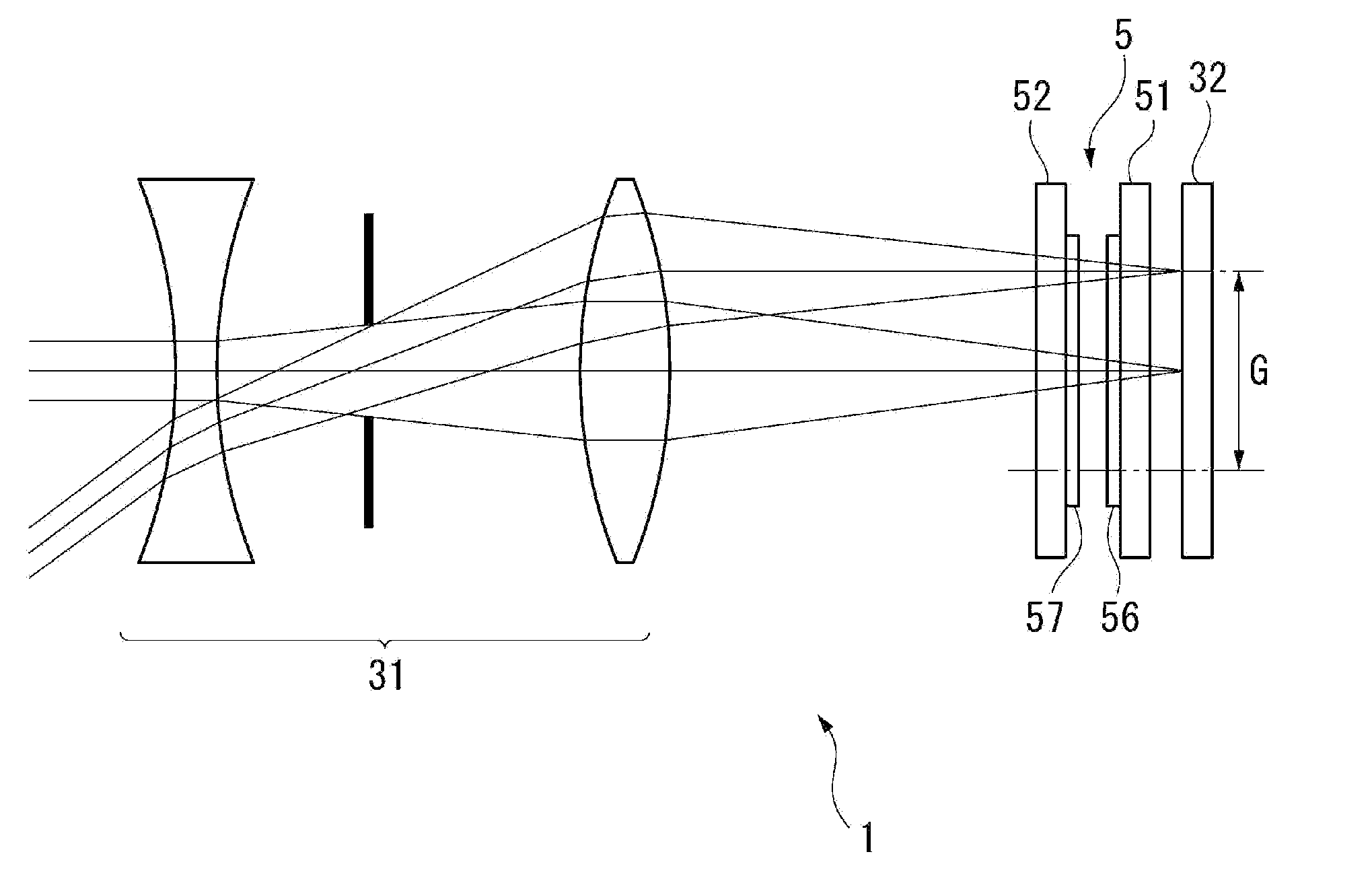
[0084]The optical device 1 according to the first embodiment described above is provided with the variable wavelength interference filter 5, the telecentric optical system 31 for guiding the incident light to the variable wavelength interference filter 5, and the detection section 32. Further, the telecentric optical system 31 is an image side telecentric optical system, and emits the light beam having the principal ray parallel to the optical axis and perpendicular to the plane of the first reflecting film 56 toward the variable wavelength interference filter 5. Further, the telecentric optical system 31 inputs the incident light within the range of the field angle to the effective measurement area G where the wavelength of the transmitted light is within the allowable value λ0 from the measurement center wavelength λ1.
[0085]Specifically, assuming that the gap dimension on the center axis O of the movable section 521 is d1, the telecentric o...
second embodiment
Action and Advantages of Second Embodiment
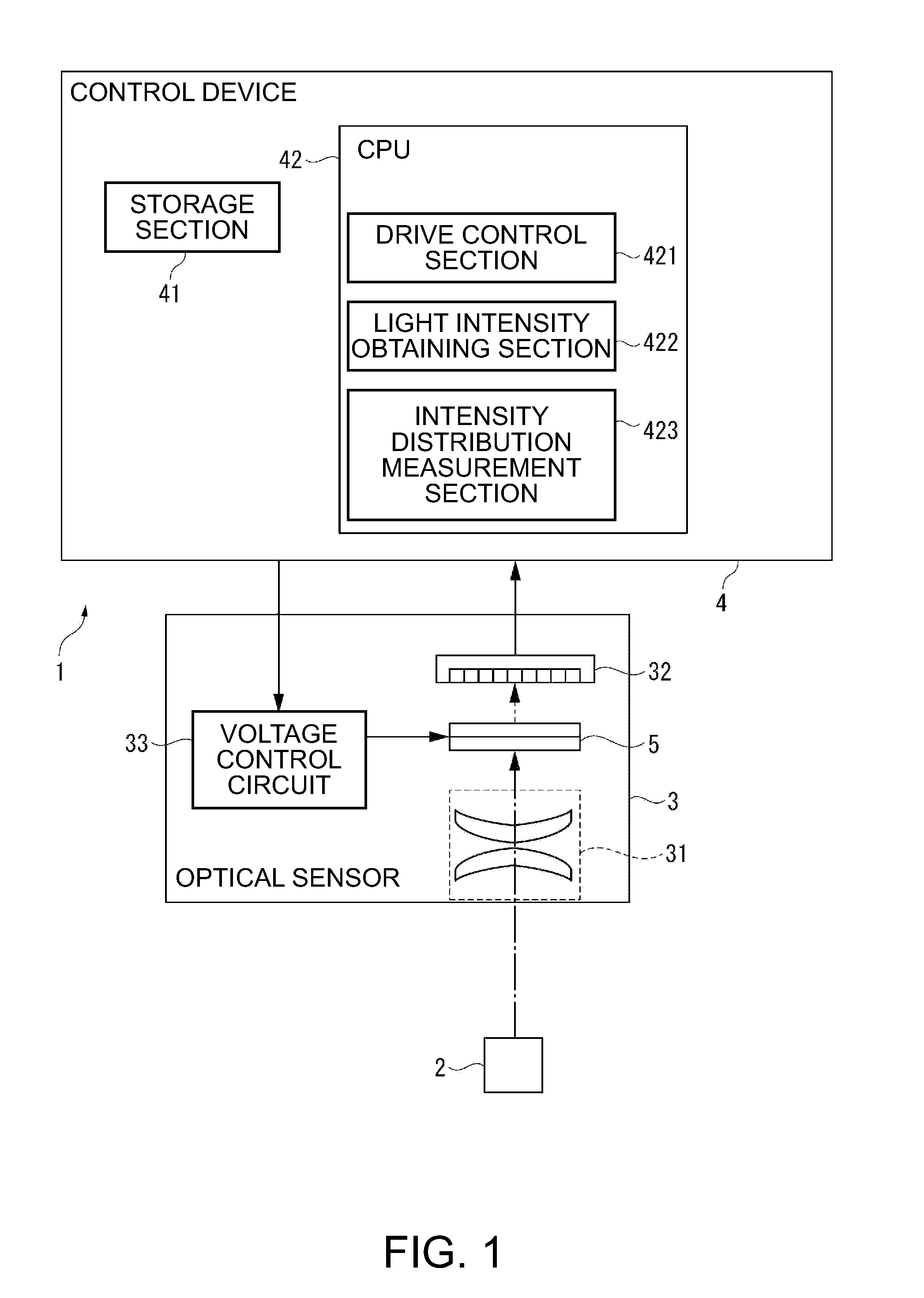
[0094]In the optical device 1A according to the second embodiment described above, the first circularly polarizing plate 34 is disposed between the telecentric optical system 31 and the variable wavelength interference filter 5, and the first circularly polarizing plate 34 is composed of the linearly polarizing plate 341 facing to the telecentric optical system 31 and the ¼-wave plate 342 facing to the variable wavelength interference filter 5 combined with each other.
[0095]Therefore, the first circularly polarizing plate 34 can transmit the incident light from the telecentric optical system 31 toward the variable wavelength interference filter 5, and absorb the light reflected by the variable wavelength interference filter 5. Thus, there is no chance for the light reflected by the variable wavelength interference filter 5 to return to the telecentric optical system 31, and thus, the moire fringes or the ghost caused by such a reflected wave...
third embodiment
Action and Advantages of Third Embodiment
[0102]In the optical device 1B according to the third embodiment described above, the second circularly polarizing plate 35 is disposed between the variable wavelength interference filter 5 and the detection section 32, and the second circularly polarizing plate 35 is composed of the ¼-wave plate 351 facing to the variable wavelength interference filter 5 and the linearly polarizing plate 352 facing to the detection section 32 combined with each other.
[0103]Therefore, the second circularly polarizing plate 35 can transmit the incident light from the variable wavelength interference filter 5 toward the detection section 32, and absorb the light reflected by the detection section 32. Thus, since there is no chance for the light reflected by the detection section 32 to return to the variable wavelength interference filter 5, and therefore there is no chance for the multiple interference to be caused again in such reflected wave in the gap of the...
PUM
 Abstract
Description
Claims
Application Information