
Polarizing photochromic articles

a photochromic and polarizing technology, applied in the field of photochromic articles, can solve the problems of conventional photochromic, limited in their ability to store or display information, and not well suited for low-light conditions

Active Publication Date: 2012-05-17
TRANSITIONS OPTICAL INC
View PDF1 Cites 57 Cited by
  • Summary
  • Abstract
  • Description
  • Claims
  • Application Information

AI Technical Summary

Benefits of technology

[0018]With the at least three-layered embodiment, the third unactivated state terminal minimum absorbance wavelength (of the second photochromic compound of the topcoat layer) is less than the second unactivated state terminal minimum absorbance wavelength (of the photochromic-dichroic compound of ...

Problems solved by technology

Thus, while conventional linearly polarizing elements are useful in reducing reflected light glare, because of their tint, they are typically not well suited for use under low-light conditions.
Further, because conventional linearly polarizing elements have only a single, tinted linearly polarizing state, they are limited in their ability to store or display information.
Conventional photochromic elements, however, that do not include linearly polarizing filters are generally not capable of linearly polarizing radiation.
Therefore, conventional photochromic elements are not capable of reducing reflected light glare to the same extent as conventional linearly polarizing elements.
In addition, conventional photochromic elements have a limited ability to store or display information.

Method used


Image

  • Polarizing photochromic articles
  • Polarizing photochromic articles
  • Polarizing photochromic articles

Examples


examples

[0472]Part 1 describes the preparation of the primer layer formulation (PLF). Part 2 describes the preparation of the liquid crystal alignment formulation (LCAF). Part 3 describes the preparation of the coating layer formulation (CLF). Part 4 describes the preparation of the topcoat layer formulation (TLF). Part 5 describes the procedures used for preparing the substrate and stack of coatings listed in Table 1. Part 6 describes the photochromic performance tests including the absorption ratio and optical response measurements reported in Table 1 for Comparative Examples (CE) 1 to 4 and Examples 1 to 4.

Part 1—Preparation of the PLF

[0473]Into a suitable container equipped with a magnetic stir-bar the following materials were added in the amounts indicated:[0474]Polyacrylate polyol (14.69 g) (Composition D of Example 1 in U.S. Pat. No. 6,187,444, which polyol disclosure is incorporated herein by reference, except that in Charge 2, the styrene was replaced with methyl methacrylate and 0...


PUM


Abstract

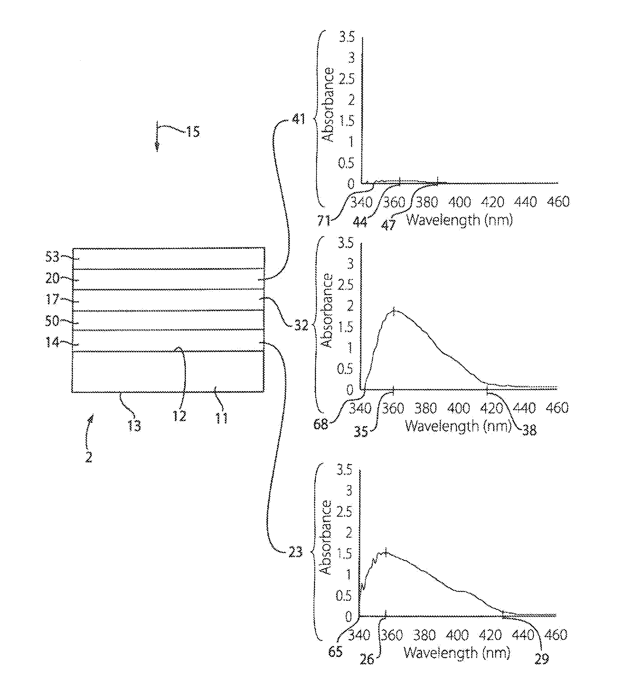
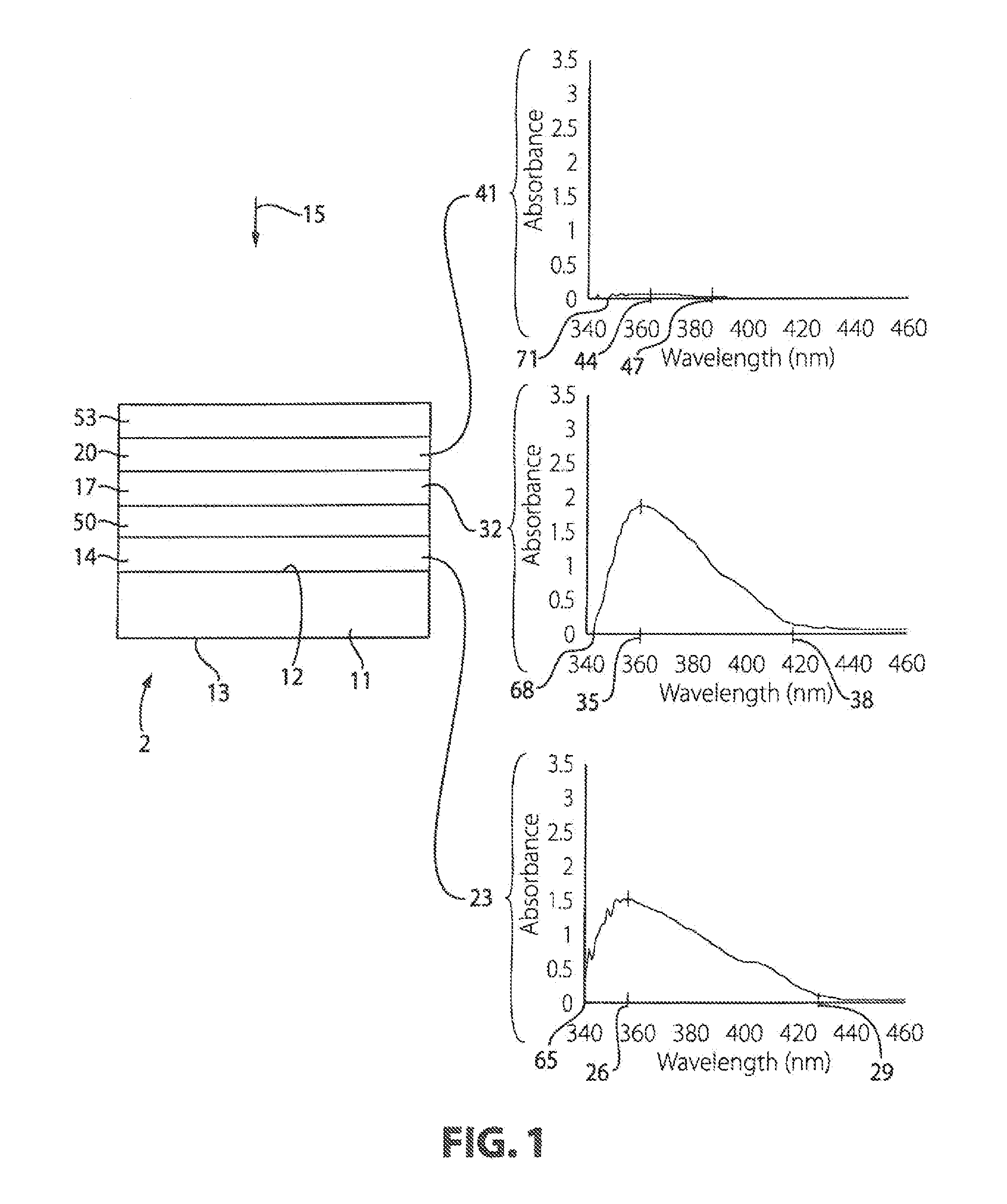
Provided are photochromic articles including a substrate, a primer layer that includes a first photochromic compound, and a photochromic-dichroic layer over the primer layer that includes a photochromic-dichroic compound. The first photochromic compound and the photochromic-dichroic compound each are selected such that the photochromic-dichroic compound has an unactivated state terminal minimum absorbance wavelength that is less than or equal to the unactivated state terminal minimum absorbance of the underlying first photochromic compound. The present invention also relates to such photochromic articles that further include a topcoat layer over the photochromic-dichroic layer, the topcoat layer including a second photochromic compound that has an unactivated state terminal minimum absorbance wavelength that is less than the unactivated state terminal minimum absorbance wavelength of the underlying photochromic-dichroic compound.

Description

CROSS REFERENCE TO RELATED APPLICATIONS[0001]This application is a continuation-in-part of U.S. patent application Ser. No. 13 / 153,748 filed on Jun. 6, 2011, which is a continuation-in-part of U.S. patent application Ser. No. 11 / 590,055 filed Oct. 31, 2006, which is a divisional of U.S. patent application Ser. No. 10 / 846,650, filed May 17, 2004 (issued as U.S. Pat. No. 7,256,921 B2), which claims and is entitled to the benefit of priority from U.S. Provisional Patent Application No. 60 / 484,100, filed Jul. 1, 2003, each of which is incorporated herein by reference in its entirety.FIELD OF THE INVENTION[0002]The present invention relates to photochromic articles that include a substrate, a primer layer that includes a first photochromic compound, and a photochromic-dichroic layer over the primer layer that includes a photochromic-dichroic compound, in which the first photochromic compound and the photochromic-dichroic compound are each selected such that the photochromic-dichroic comp...

Claims


Application Information

Patent Timeline
IPC IPC(8): G02B5/23
CPCC09B57/00C09B67/0083G02F1/1335G02B5/23C09K19/60
Inventor KUMAR, ANILYOEST, RACHAEL L.LI, CHENGUANGJACKSON, DELWIN S.NGUYEN, HENRY
Owner TRANSITIONS OPTICAL INC
Learn More