Spin-torque oscillator for microwave assisted magnetic recording

a technology of spin-torque oscillator and assisted magnetic recording, which is applied in the field of spin-torque oscillator for microwave assisted magnetic recording, can solve the problems of insufficient recording assistance, inability to generate magnetic field, and inability to fix the spin state of magnetization for a long time, so as to reduce the dimension of saturation magnetization, large assisted magnetic field strength, and stable oscillation

Inactive Publication Date: 2012-05-17
HITACHI LTD
View PDF2 Cites 14 Cited by
  • Summary
  • Abstract
  • Description
  • Claims
  • Application Information

AI Technical Summary

Benefits of technology

[0015]Since a demagnetizing field that reduces the dimension of saturation magnetization can be reduced when the structure according to the present invention is used, large assisted magne

Problems solved by technology

When oscillation is unstable and magnetization spin is not uniform in the same direction, that is, in a case of a state of multiple magnetic domains, a spun state of magnetization may not be fixed for time.
In this case, magnetic field strength generated from FGL is not fixed for time and a problem that recording cannot be sufficiently assisted occurs.
However, since

Method used


Image

  • Spin-torque oscillator for microwave assisted magnetic recording
  • Spin-torque oscillator for microwave assisted magnetic recording
  • Spin-torque oscillator for microwave assisted magnetic recording

Examples


first embodiment

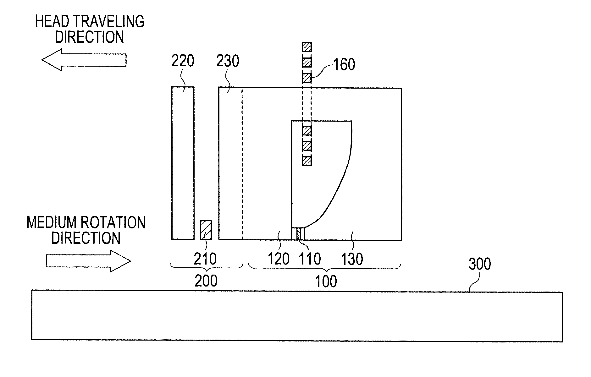
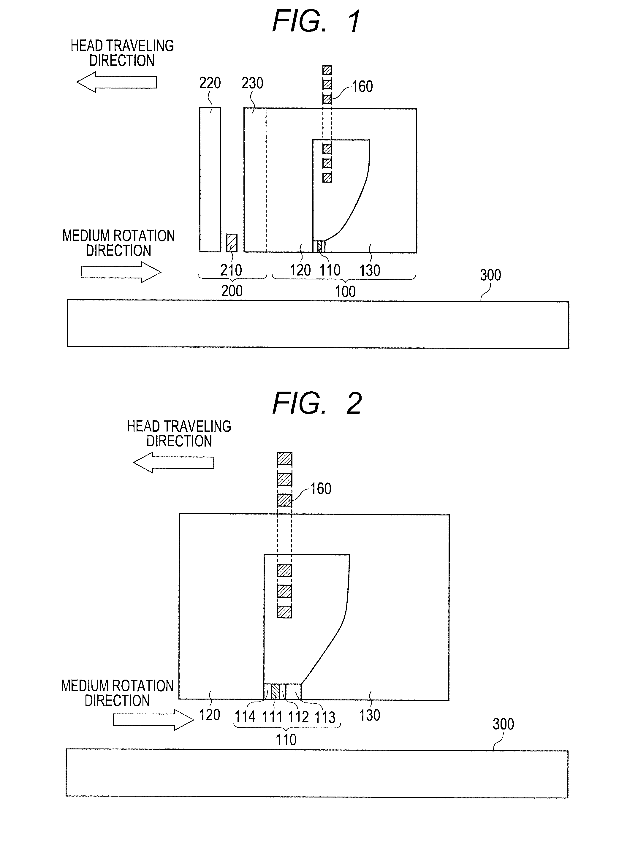
[0035]FIG. 1 is a schematic diagram showing a magnetic recording / reproducing head provided with an oscillator according to the present invention in a disk unit including the magnetic recording / reproducing head that records and reproduces data and a magnetic record medium 300 on which the recording and the reproduction of data are performed by the magnetic recording / reproducing head.

[0036]The magnetic recording / reproducing head shown in FIG. 1 is configured by a recording head part 100 and a reproducing head part 200. The recording head part 100 is configured by the oscillator 110 for generating a high-frequency field, a main pole 120 for generating a recording head magnetic field and a coil 160 for magnetizing the main pole. Further, a trailing shield 130 can be provided in a trailing direction of the main pole. In this case, the trailing direction is defined as a direction reverse to a traveling direction of the head over the medium and a leading direction is defined as the traveli...

second embodiment

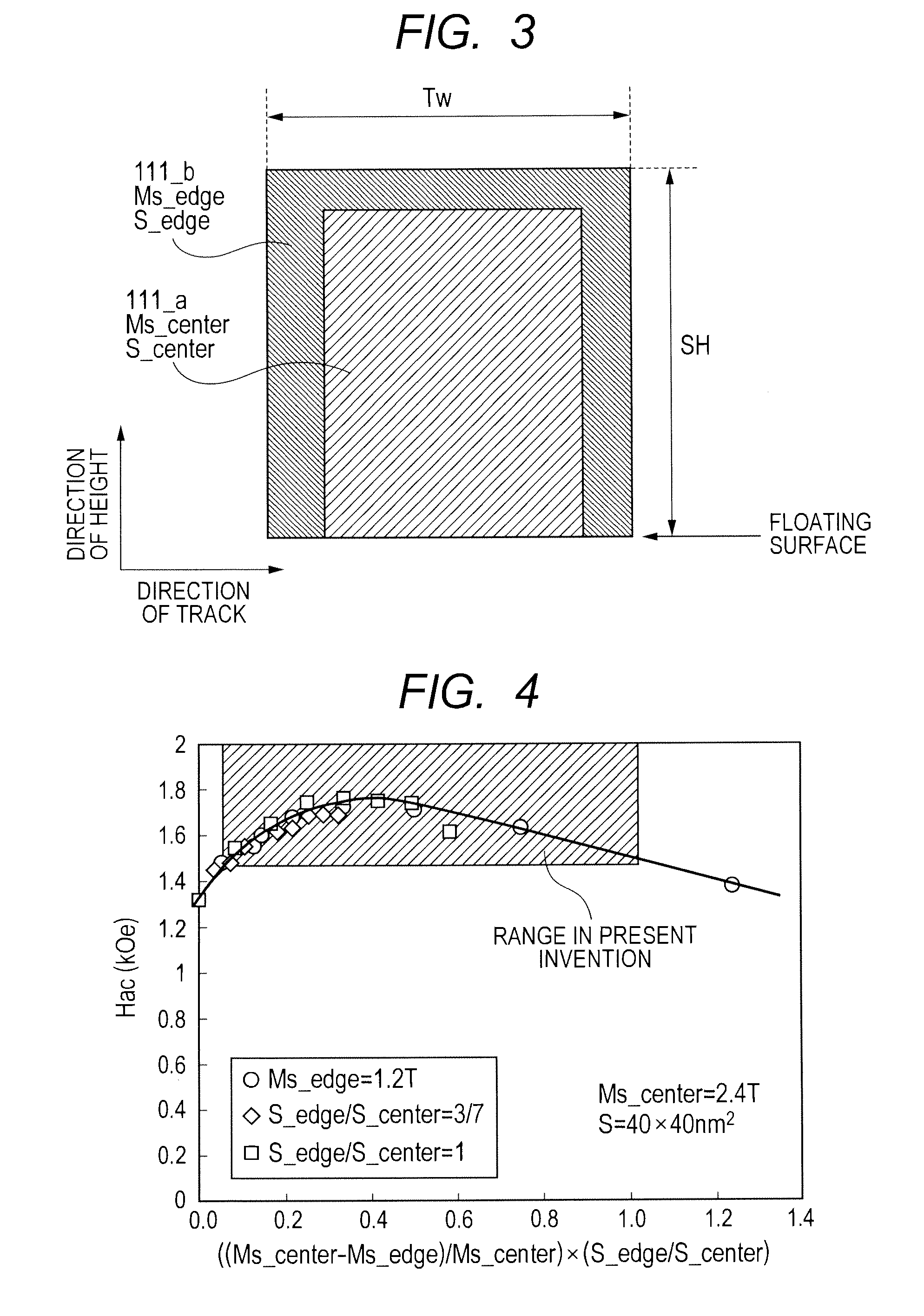
[0061]FIG. 13 shows a second embodiment of the present invention. In this embodiment, as in the first embodiment, FGL 111 is in the shape of a rectangle in which the height SH of the FGL 111 in a direction from an air bearing surface to a surface opposite to it is larger than the length Tw in a direction of track width. Since the distance between ends in the direction of track width of the FGL is shorter than an end in the direction of the height of the FGL when saturation magnetization is uniform in such a shape, a dimension of a demagnetizing field increases. Therefore, magnetization at the end of the FGL in the direction of track width cannot be spun as magnetization in another part and it is a main cause that inhibits single domain oscillation. Accordingly, in this shape, it is required to further reduce a dimension of a demagnetizing field at the end in the direction of track width of the FGL 111.

[0062]Then, as in this embodiment, when the saturation magnetization Ms of a regio...

third embodiment

[0064]FIG. 14 shows a third embodiment of the present invention. FGL 111 in this embodiment is in the shape of a rectangle. Unlike the second embodiment, the length Tw in a direction of track width is larger than the height SH in a direction of the height of FGL 111. Accordingly, in this case, a dimension of a demagnetizing field at an end in the direction of the height of the FGL 111 is larger than that at an end in the direction of track width and it is a main cause that inhibits single domain oscillation. In this shape, the dimension of a demagnetizing field at the end of the FGL in the direction of the height can be further reduced by further enlarging a region S_edge in which the quantity of magnetization is reduced in a part 111—b in which the quantity of magnetization is reduced at the end of the FGL 111 in the direction of the height as described in the second embodiment or reducing saturation magnetization Ms and further, simultaneously controlling both. As a result, the di...


PUM


Abstract

In a conventional type magnetic head that performs microwave assisted recording, since a difference in a demagnetizing field between an end and the center of a field generation layer (FGL) grows larger when saturation magnetization of the FGL grows larger, the FGL that generates a microwave is not oscillated in a state of a single domain. Then, a spin-torque oscillator according to the present invention used for a magnetic head for microwave assisted recording is provided with at least one fixed layer, one non-magnetic intermediate layer and one alternating-current magnetic field generation layer respectively and is provided with a structure where saturation magnetization at ends of a film except an end in a direction from an air bearing surface to a surface opposite to it is made smaller than saturation magnetization in the center of the film of the alternating-current magnetic field generation layer.

Description

INCORPORATION BY REFERENCE[0001]The present application claims priority from Japanese application serial No. 2010-255700, filed on Nov. 16, 2010, the entire contents of which are hereby incorporated by reference into this application.FIELD OF THE INVENTION[0002]The present invention relates to a structure for stably oscillating a field generation layer (FGL) in a magnetic head for microwave assisted recording in a state of a single domain.BACKGROUND OF THE INVENTION[0003]The miniaturization of the bit size of a record medium is promoted according to the enhancement of the recording density of a hard disk drive (HDD). However, as the miniaturization of the bit size is advanced, the extinction by thermal fluctuation of a recorded state is feared. To settle such a problem and to stably maintain a bit in future high density recording, it is required to use a record medium the coercive force of which is large (that is, the magnetic anisotropy of which is large). However, a strong recordi...

Claims


Application Information

Patent Timeline
IPC IPC(8): G11B5/02
CPCG11B2005/0024G11B5/3146
Inventor MATSUBARA, MASATOSHIIMOTO, MASATOKATADA, HIROYUKINAGASAKA, KEIICHI
Owner HITACHI LTD
Why Eureka
Try Eureka