Light-bulb type LED lamp and illumination apparatus

a technology of led lamps and illumination apparatus, which is applied in the direction of lighting and heating apparatus, semiconductor devices for light sources, lighting support devices, etc., can solve the problems of reducing the brightness of one led compared to the brightness of a halogen light bulb, consuming less energy, and reducing the heat of one led compared to the other, so as to reduce the effect of heat from one led and heat from one led

Active Publication Date: 2012-05-17
PANASONIC CORP
View PDF25 Cites 13 Cited by
  • Summary
  • Abstract
  • Description
  • Claims
  • Application Information

AI Technical Summary

Benefits of technology

[0011]With the above structure for the light-bulb type LED lamp, LEDs are provided along the circumferential direction around the central axis of the bowl-shaped portion. Therefore, any one LED on any one of the stages is not surrounded by other LEDs. Furthermore, a section of the bowl-shaped portion is located between any one LED and the LEDs provided on an adjacent stage (adjacent to the stage on which the one LED is provided). Therefore, as compared to a conventional structure in which LEDs are provided in the same plane, the heat dissipation route between the LEDs is correspondingly longer, thus reducing the effect of heat from one LED on another. Moreover, since the section of the bowl-shaped portion is exposed to air, a large portion of heat is thought to dissipate along this section. This is another reason why the effect of heat from one LED on another is reduced. Variation in temperature between LEDs during lighting is thus reduced as compared to a conventional structure. Accordingly, variation in luminous efficiency between LEDs is reduced in so far as possible.
[0012]Of further note is how LEDs are provided in the circumferential direction on at least two stages, i.e. LEDs are provided in at least two tiered rings. It is therefore unnecessary to reduce the number of LEDs, unlike in the above conventional LED lamp, in which only one ring of LEDs is provided in order to reduce unevenness in luminous efficiency.
[0013]In order to solve the above problems, a light-bulb type LED lamp according to the present invention comprises a plurality of LEDs; a base; a lighting circuit configured to convert commercial power provided through the base into power for lighting the LEDs; and a heat radiation member having a bowl-shaped portion, individual stages, each extending inwards from an inner circumferential surface of the bowl-shaped portion, being provided for the LEDs in one-to-one correspondence, each LED being mounted on a mounting surface on the corresponding individual stage, the individual stages being arranged so that when viewing the LEDs from a central axis of the bowl-shaped portion, none of the LEDs is aligned with any other LED, and an angle of the mounting surface being changeable.
[0014]With the above structure for the light-bulb type LED lamp, LEDs are mounted on individual stages extending inwards from the inner circumferential surface of the bowl-shaped portion. Therefore, a section of the bowl-shaped portion is located between an individual stage on which an LED is mounted and an individual stage on which another LED is mounted. Therefore, as compared to a conventional structure in which LEDs are provided in the same plane, the heat dissipation route between the LEDs is correspondingly longer, thus reducing the effect of heat from one LED on another. Moreover, since the section of the bowl-shaped portion is exposed to air, a large portion of heat is thought to dissipate along this section. This is another reason why the effect of heat from one LED on another is reduced. Variation in temperature between LEDs during lighting is thus reduced as compared to a conventional structure. Accordingly, variation in luminous efficiency between LEDs is reduced in so far as possible.
[0015]Furthermore, the individual stages may be provided at any position along the inner circumferential surface as long as LEDs do not align when viewed in the radial direction from the bowl-shaped portion. It is therefore unnecessary to reduce the number of LEDs, unlike in the above conventional LED lamp, in which only one ring of LEDs is provided in order to reduce unevenness in luminous efficiency.
[0016]Of further note is how the angle of the LED mounting surface on each individual stage can be changed, thus allowing for the light-distribution characteristics of the lamp to be changed.

Problems solved by technology

These light-bulb type LED lamps have a longer life expectancy and consume less energy than halogen lamps.
While some LEDs offer an amazing level of brightness, one LED still pales in comparison to the brightness offered by a halogen light bulb.

Method used


Image

  • Light-bulb type LED lamp and illumination apparatus
  • Light-bulb type LED lamp and illumination apparatus
  • Light-bulb type LED lamp and illumination apparatus

Examples


embodiment 1

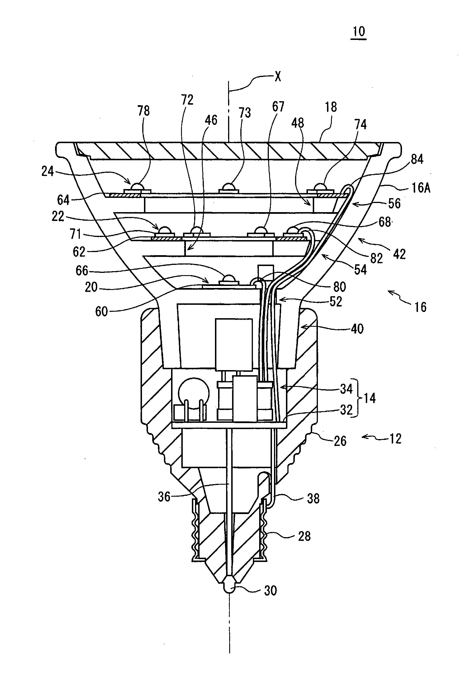
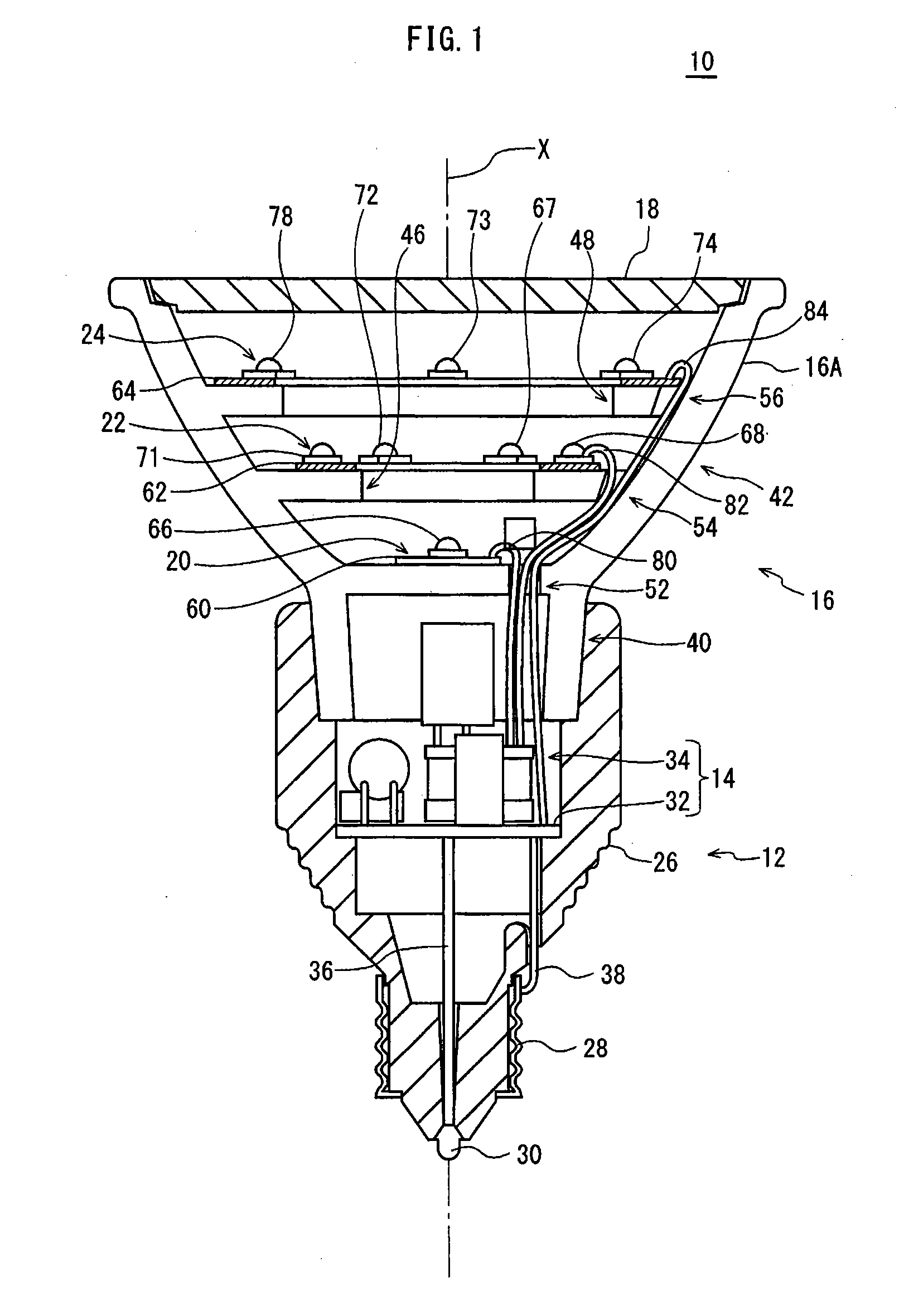
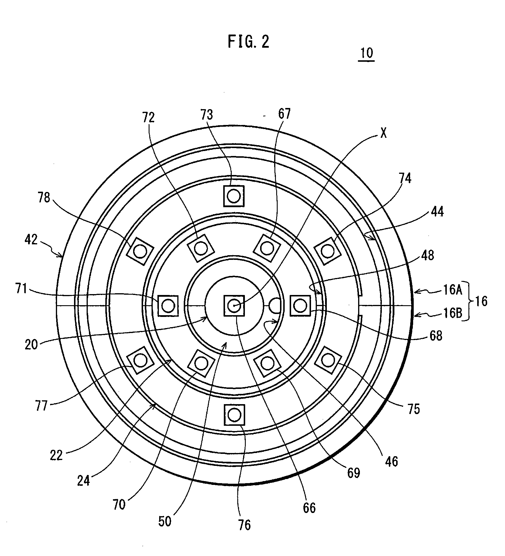
[0028]FIG. 1 is a front cross-section diagram of a light-bulb type LED lamp 10 according to Embodiment 1 (hereinafter simply referred to as “LED lamp 10”). FIG. 2 is a plan view of the same. Note that FIG. 2 depicts the LED lamp 10 without a front glass 18. The front glass 18 is described below.

[0029]The LED lamp 10 is formed by a base 12, a lighting circuit unit 14, a heat radiation member 16, the front glass 18, LED modules 20, 22, 24, and the like.

[0030]The base 12 has a main body 26 formed by electric insulating material. One end of the main body 26 is generally cylindrical. A shell 28 is fit onto the generally cylindrical portion. One end of the cylindrical portion is in the approximate shape of a truncated cone. An eyelet 30 is fixed to the tip of the truncated cone. The base 12 conforms to a standard (such as the JIS standard) for attachment to a socket of a conventional lighting fixture for incandescent light bulbs.

[0031]The other end of the cylindrical portion of the main b...

embodiment 2

[0057]FIG. 4 is a front cross-section diagram of a light-bulb type LED lamp 100 according to Embodiment 2 (hereinafter simply referred to as “LED lamp 100”). FIG. 4 is drawn similar to FIG. 1.

[0058]The LED lamp 100 according to Embodiment 2 has a structure similar to the LED lamp 10 (FIG. 1) according to Embodiment 1, except for the shape of the heat radiation member. Accordingly, constituent elements that are similar to the LED lamp 10 are labeled with the same reference signs, and an explanation thereof is omitted. The following focuses on the differences between the LED lamps 100 and 10.

[0059]In order to increase the volume of a heat radiation member 102 in Embodiment 2, a first stage 104 and a second stage 106 differ from the first stage 46 and the second stage 48 in Embodiment 1 in that the lower side of the first stage 104 and the second stage 106 are filled in with material for forming the heat radiation member 102 (in this embodiment, aluminum) with almost no open space prov...

embodiment 3

[0061]In Embodiments 1 and 2, the first stage 46 or 104 and the second stage 48 or 106 are formed as rings centering on the central axis X (i.e. formed integrally around the central axis X). On the other hand, in the light-bulb type LED lamp according to Embodiment 3 (hereinafter simply referred to as “LED lamp”), the stages are divided into a plurality of sections in the circumferential direction, and the angle of each section (i.e. LED mounting surface in each individual stage) is changeable.

[0062]The base 12, the lighting circuit unit 14, the front glass 18, and the LEDs 67-78 are the same in Embodiment 3 as in Embodiments 1 and 2. Therefore, these components are omitted from the drawings and from the description below, which focuses on the differences in Embodiment 3.

[0063]FIG. 5A is a perspective view of a first member 202A in the LED lamp according to Embodiment 3, in which a first member and a second member form a heat radiation member having a neck and a bowl-shaped portion....


PUM


Abstract

Provided is a light-bulb type LED lamp 10 including a plurality of LEDs 67-78, a base 12, a lighting circuit unit that converts commercial power provided through the base 12 into power for lighting the LEDs 67-78, and a heat radiation member 16 that includes a bowl-shaped portion 42. Two stages 46 and 48, extending inwards from an inner circumferential surface 44 of the bowl-shaped portion 42, are provided in a direction of a central axis X of the bowl-shaped portion 42. The LEDs 67-78 are mounted on the stages 46 and 48 in a circumferential direction around the central axis X.

Description

TECHNICAL FIELD[0001]The present invention relates to a light-bulb type LED lamp and an illumination apparatus, such as a light-bulb type LED lamp that is a suitable light source as a replacement for a reflector halogen light bulb, and an illumination apparatus provided with the light-bulb type LED lamp.BACKGROUND ART[0002]A reflector halogen light bulb combines a halogen light bulb with a bowl-shaped reflector having a concave reflecting surface. Such a reflector halogen light bulb is, for example, mounted in a downlight fixture and used as a spotlight in stores, galleries, or the like.[0003]In order to decrease the frequency of replacement, which depends on the light bulb's life expectancy, while also promoting energy efficiency, light-bulb type light emitting diode (LED) lamps that use LEDs as a light source are being developed. These light-bulb type LED lamps have a longer life expectancy and consume less energy than halogen lamps. To serve as an alternative light source to refl...

Claims


Application Information

Patent Timeline
Patent Type & Authority Applications(United States)
IPC IPC(8): F21V21/14F21V29/00
CPCF21K9/1375F21K9/58F21Y2111/008F21V19/02F21Y2101/02F21V14/02F21K9/23F21K9/65F21V23/002F21Y2107/60F21Y2115/10
Inventor UEMOTO, TAKAARIKAWAGOE, SHINYAHASHIMOTO, NAOTAKAKOJIMA, TOSHIYASUIKEDA, TAKUUEDA, YASUYUKINAGAI, HIDEONOHARA, HIROSHI
Owner PANASONIC CORP
Why Eureka
Try Eureka