Wireless access point clock synchronization system

a technology of wireless access point and clock synchronization, which is applied in the direction of synchronisation arrangement, wireless commuication services, electrical appliances, etc., can solve the problems of relatively difficult to modify the physical configuration of the aps and the installation is relatively expensive, so as to avoid unnecessary proliferation of numbers

Inactive Publication Date: 2012-05-17
DECAWAVE
View PDF30 Cites 35 Cited by
  • Summary
  • Abstract
  • Description
  • Claims
  • Application Information

AI Technical Summary

Benefits of technology

[0029]In the drawings, similar elements will be similarly numbered whenever possible. However, this practice is simply for convenience of reference and to avoid unnecessary proliferation of numbers, and is not intended to imply or suggest that our invention requires identity in either function or structure in the several embodiments.

Problems solved by technology

Furthermore, it is of no relevance in such systems which specific voltage levels are selected to represent each of the logic states.
For example, it is possible to achieve clock synchronization using wired distribution of a master clock signal to each AP; but such an implementation is relatively expensive to install and relatively difficult thereafter to modify the physical configuration of the APs.

Method used


Image

  • Wireless access point clock synchronization system
  • Wireless access point clock synchronization system
  • Wireless access point clock synchronization system

Examples


Embodiment Construction

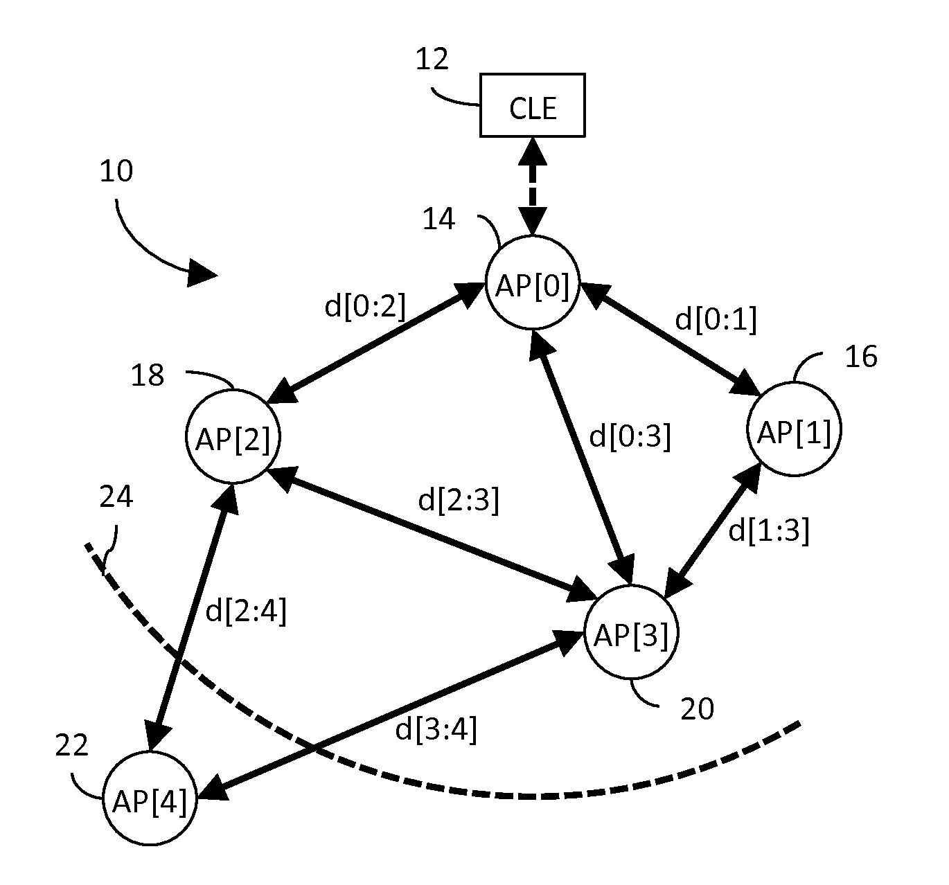
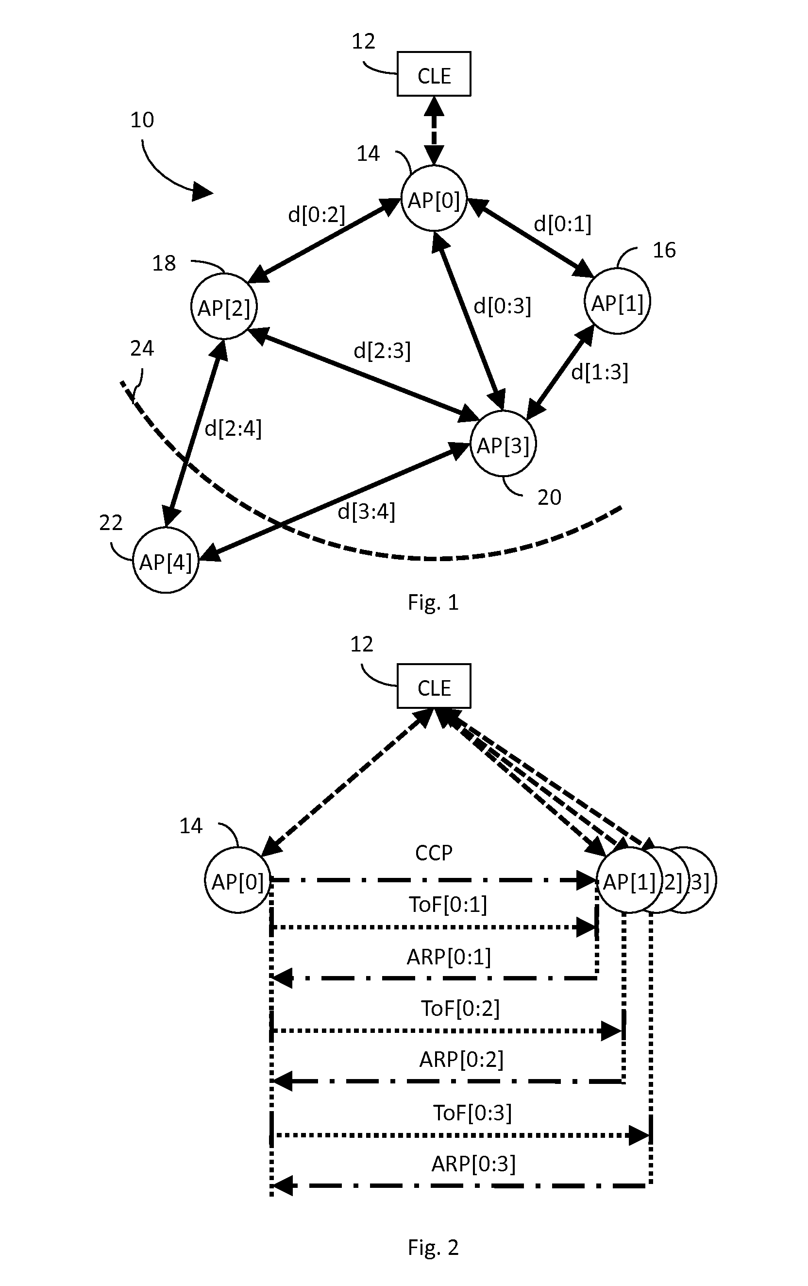
[0030]Shown in FIG. 1 is a UWB network 10 comprising a central location engine (CLE) 12 and a plurality of APs: AP[0]14; AP[1]16; AP[2]18; AP[3]20; and AP[4]22; each AP generally comprising a conventional UWB transmitter, receiver and associated control (all not shown for clarity). In the illustrated topology, the physical distance, d, between each pair of APs is depicted as a bi-directional arrow connecting the AP pair, and labeled with the respective distance, d[x:y], where x indicates the first AP of the pair and y indicates the second AP of the pair. By way of illustration, we have shown AP[1-3] as all being within the effective transmission range of AP[0], indicated by dashed arc 24, whereas AP[4] is outside that range and thus must be accessed via either AP[2] or AP[3].

[0031]In network 10, a primary responsibility of the CLE 12 is to synchronize the timebases of all APs so as to assure normalized time references with respect to mobile tag-related reports. As is known, the topo...


PUM


Abstract

In an ultra-wideband (“UWB”) network, a central location engine (“CLE”) coordinates operation of an anchor access point (“AP”), AP[0], and a plurality of non-anchor AP[x]s. A clock calibration packet (“CCP”) transmission method and related apparatus facilitate normalization of CCP time references reported to the CLE by all APs. Implementing a digital phase locked loop (“DPLL”) in the CLE facilitates clock normalization. Implementing a DPLL in at least the non-anchor AP[x]s facilitates local clock synchronization, and may improve network efficiency by reducing clock synchronization traffic.

Description

BACKGROUND OF THE INVENTION[0001]1. Field of the Invention[0002]The present invention relates generally to wireless access point systems, and, in particular, to clock synchronization in a wireless access point system.[0003]2. Description of the Related Art[0004]In general, in the descriptions that follow, we will italicize the first occurrence of each special term of art which should be familiar to those skilled in the art of ultra-wideband (“UWB”) communication systems. In addition, when we first introduce a term that we believe to be new or that we will use in a context that we believe to be new, we will bold the term and provide the definition that we intend to apply to that term. In addition, throughout this description, we will sometimes use the terms assert and negate when referring to the rendering of a signal, signal flag, status bit, or similar apparatus into its logically true or logically false state, respectively, and the term toggle to indicate the logical inversion of ...

Claims


Application Information

Patent Timeline
Patent Type & Authority Applications(United States)
IPC IPC(8): H04W56/00H04W88/08
CPCH04W56/002
Inventor MCLAUGHLIN, MICHAELVERSO, BILLY
Owner DECAWAVE
Why Eureka
Try Eureka