Support Frame of Glass Brick Wall and Method for Mounting the Same

a technology of glass brick wall and support frame, which is applied in the direction of fixed installation, building repairs, lighting and heating equipment, etc., can solve the problems of messed up indoor environment, unable to afford additional expenditure, and difficulty in cleaning up hardened plaster, etc., and achieve the effect of convenient replacemen

Active Publication Date: 2012-05-24
KUO YUAN LUN
View PDF12 Cites 5 Cited by
  • Summary
  • Abstract
  • Description
  • Claims
  • Application Information

AI Technical Summary

Benefits of technology

[0008]An objective of the present invention is to provide a support frame assembled with a glass brick wall and having lighting sources mounted in the support frame to be conveniently replaced.
[0017]The support frame employs the horizontal beams, the vertical beams and the side bar to bind and support glass bricks. Assembling the glass brick wall with the support frame will not mess up the environment. The mounting method of the support frame is simple, and thus, the support frame can be assembled with glass bricks to form a glass brick wall in a do-it-yourself (DIY) fashion. When a lamp strip is faulty, the faulty lamp strip can be easily replaced through the side bar. Accordingly, the support frame achieves a solution to keep the mounting environment clean and tidy during mounting, while saving extra cost for hiring workers to do the mounting and making replacement of light sources inside the glass brick wall easy and convenient.

Problems solved by technology

Dust and slurry resulting from mixing cement certainly messes up the indoor environment, and cleaning up the hardened plaster becomes another problem.
Homeowners also need to hire a constructor to work on the glass brick wall on their properties and hence have to afford an additional expenditure for that.
The thick cement layers formed inside the glass brick wall indeed dramatically reduce the aesthetic appeal of the entire glass brick wall as an indoor landscape.
However, the light sources not only occupy space but also require sufficient luminance to maintain a desired decorating and lighting effect.

Method used


Image

  • Support Frame of Glass Brick Wall and Method for Mounting the Same
  • Support Frame of Glass Brick Wall and Method for Mounting the Same
  • Support Frame of Glass Brick Wall and Method for Mounting the Same

Examples


Embodiment Construction

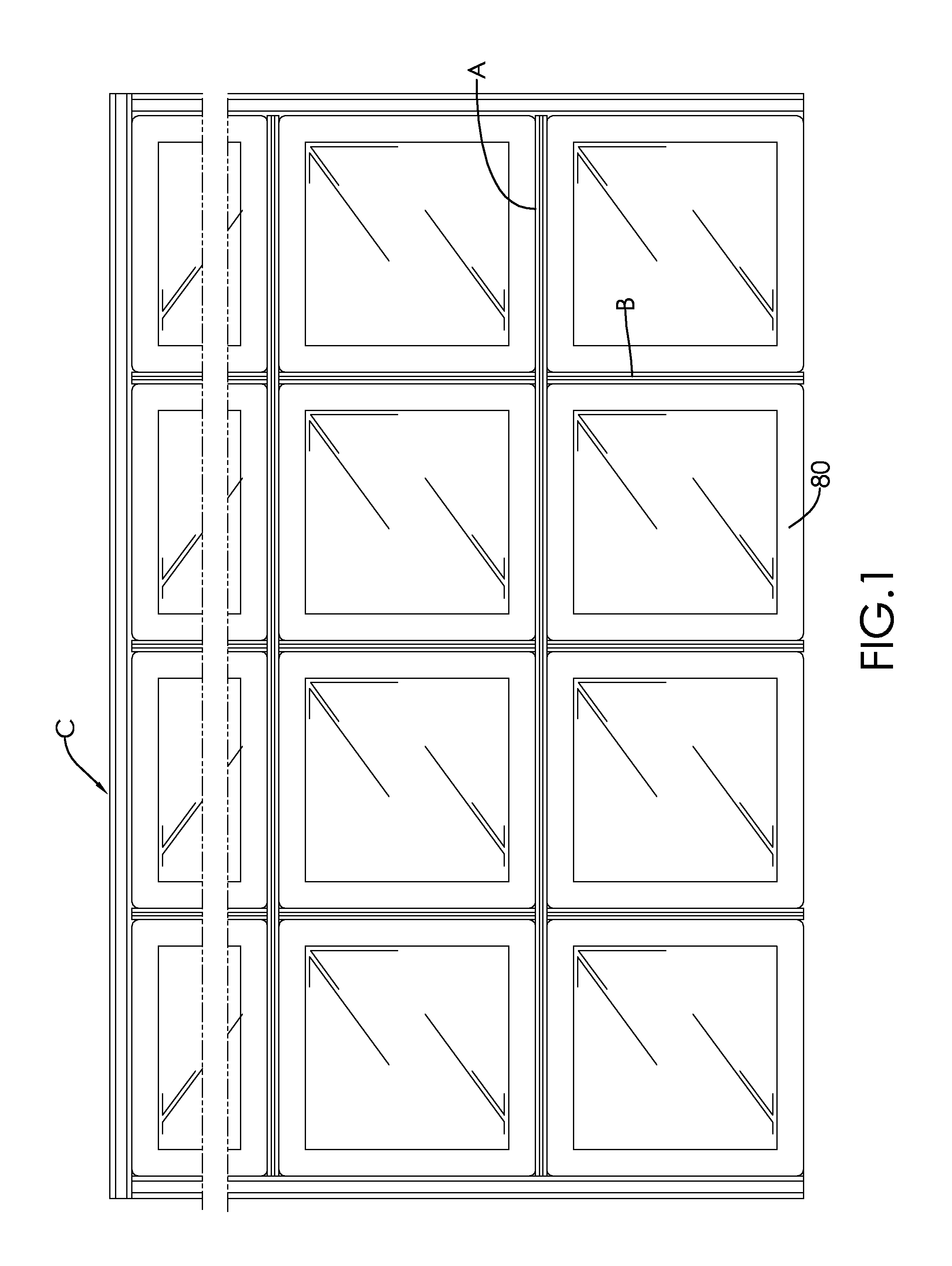
[0026]With reference to FIG. 1, a first embodiment of a support frame of glass brick wall in accordance with the present invention has multiple horizontal beams (A), multiple vertical beams (B) and multiple side bars (C).

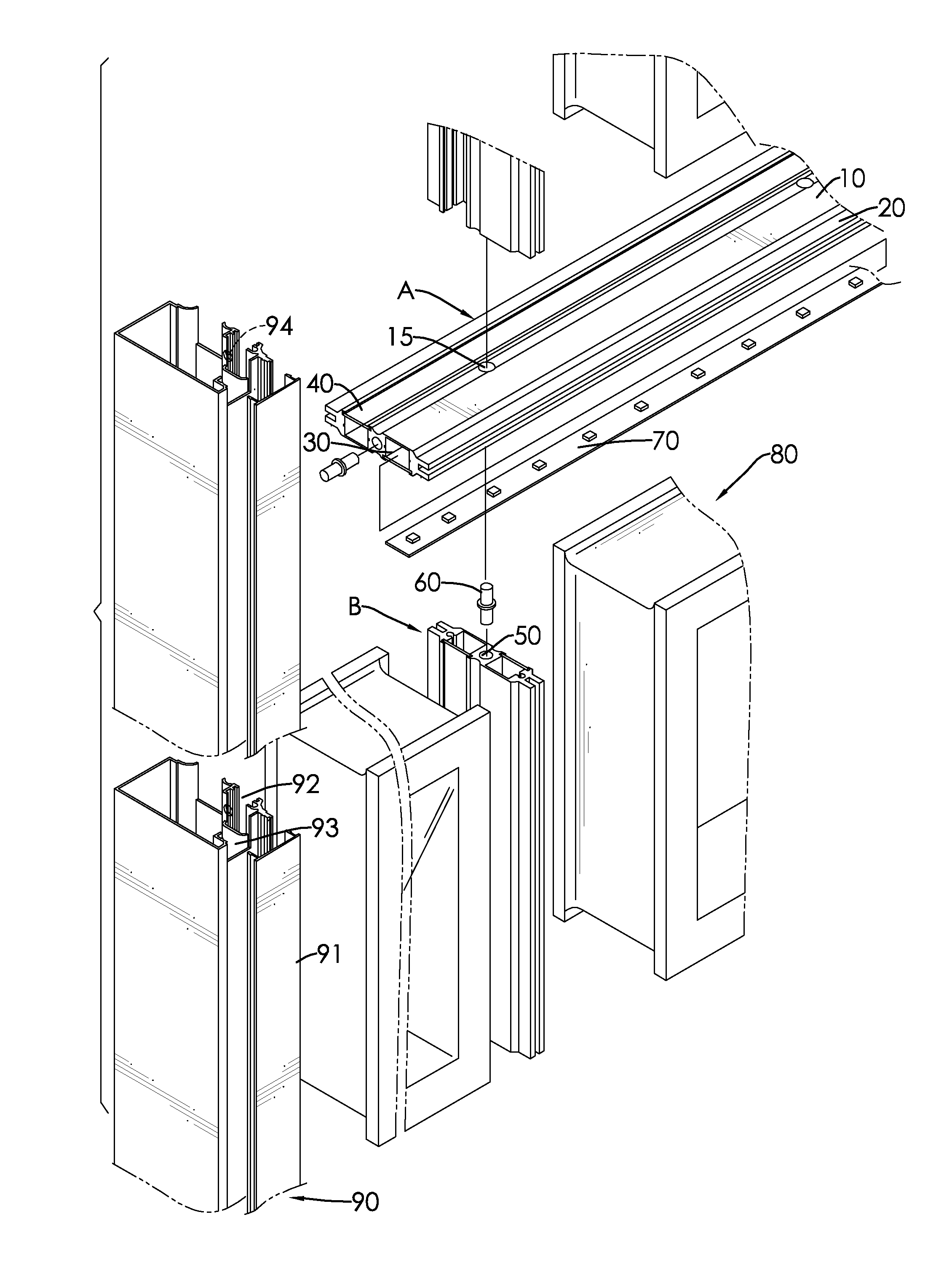
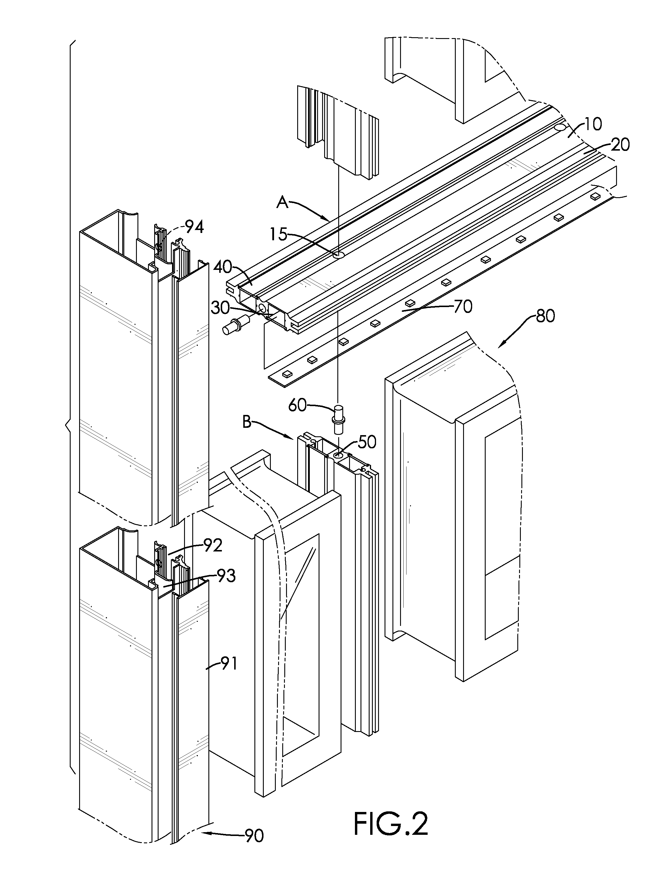
[0027]The horizontal beams (A) and the vertical beams (B) are perpendicularly mounted to support glass bricks framed by the horizontal beams (A) and the vertical beams (B). The horizontal beam (A) is exactly the same as the vertical beam (B), but the horizontal and vertical beams (A, B) may differ in length depending on the numbers of rows of glass bricks and columns of glass bricks required for a glass brick wall. With reference to FIGS. 2 to 3, each of the horizontal beam (A) and the vertical beam (B) has a body 10, two side wings 20, two lamp slots 30, two cover strips 40, a pin hole 50, a pin 60, at least one lamp strip 70 and multiple first through holes 15.

[0028]The body 10 is elongated and flat, and has a width corresponding to that of one of four edge sides ...


PUM


Abstract

A support frame of glass brick wall has multiple horizontal beams, multiple vertical beams and multiple side bars. Each of the horizontal beams and the vertical beams has a body, two side wings respectively and longitudinally formed on and protruding from two edges of the body, and two lamp slots respectively and longitudinally formed on and recessed from two sides of the body. Each of the vertical beams is securely mounted between two adjacent glass bricks in a corresponding row of glass bricks with adhesive. Each of the horizontal beams is securely mounted on a top of a corresponding row of glass bricks with adhesive. Two of the side bars are securely mounted on two edge sides of the glass brick wall. Each of the side bars has openings to replace light strips mounted in the lamp slots. Accordingly, the support frame provides a clean and easy lamp replacement solution.

Description

BACKGROUND OF THE INVENTION[0001]1. Field of the Invention[0002]The present invention relates to a support frame of a glass brick wall, and more particularly to a support frame assembled with a glass brick wall and having a lighting source mounted in the support frame and to be conveniently replaced.[0003]2. Description of the Related Art[0004]Glass brick walls are transparent, composed of cubical glass bricks and are mostly employed in interior design for enhancing aesthetic appeal and diversifying indoor layout arrangements.[0005]To be piled up, conventional glass bricks of a glass brick wall usually have gaps formed between each other so that steel bars can be respectively mounted in the gaps among the glass bricks to serve as a support frame of the entire glass brick wall. Cement is then filled into the gaps just as in the regular brick wall construction.[0006]However, as glass brick walls are mostly built indoors, cement must be placed on an empty floor in the nearby and be mix...

Claims


Application Information

Patent Timeline
Patent Type & Authority Applications(United States)
IPC IPC(8): E04C2/38E04B1/38E04C1/42
CPCE04C1/42
Inventor KUO, YUAN-LUN
Owner KUO YUAN LUN
Why Eureka
Try Eureka