Lightning protection for composite aircraft structures

a composite aircraft and protection system technology, applied in aircraft lighting protectors, aircraft static dischargers, aircraft components, etc., can solve problems such as high process cost, sparking or hot spots, and especially dangerous phenomena

Inactive Publication Date: 2012-05-24
EADS CONSTRS AERONAUTICAS
View PDF3 Cites 3 Cited by
  • Summary
  • Abstract
  • Description
  • Claims
  • Application Information

AI Technical Summary

Benefits of technology

[0011]One of the advantages of the lightning protection system of the invention is that it can comprise materials which are fully compatible with aeronautical composite materials, thus a more homogeneous structure being obtained.
[0012]Also, the system of the invention is much lighter than the known metallising structures of the prior art, since the amount of metallising needed to provide the same level of lightning protection is much lower.
[0013]A further advantage is the industrialization capability of the process for manufacturing the system according to the invention, due to the automatic nature of the process used for the deposition of conductive nanoparticles.

Problems solved by technology

Phenomena such as sparking or hot spot, which may be produced by a lightning strike on the aircraft structure, are especially dangerous when the structure is forming a fuel tank or enclosing ignitable vapours because they are potential ignition sources whenever the energy is enough to ignite the fuel vapours.
One of the difficulties presented by these embodiments is that the metallic layer is applied manually, as it is difficult to integrate it within the automatic laminate lay-up system used in the aeronautical composite production, which makes the process costly.
Besides, when the metallic layer is applied in the form of metallic strips at joints in the composite structure, there is a problem with the compatibility between the metallic material and the composite laminate in the structure, due to the differences of material properties.
Additionally, some fasteners may not be adequate as they cause large quality control problems due to the fact that small defects in the installation may be critical for the protection method to be effective.
Moreover, these embodiments also present the difficulty of making the composite structures heavy, which is a serious drawback in aeronautic structures, in which the minimisation of weight is a main object.

Method used


Image

  • Lightning protection for composite aircraft structures
  • Lightning protection for composite aircraft structures
  • Lightning protection for composite aircraft structures

Examples


Embodiment Construction

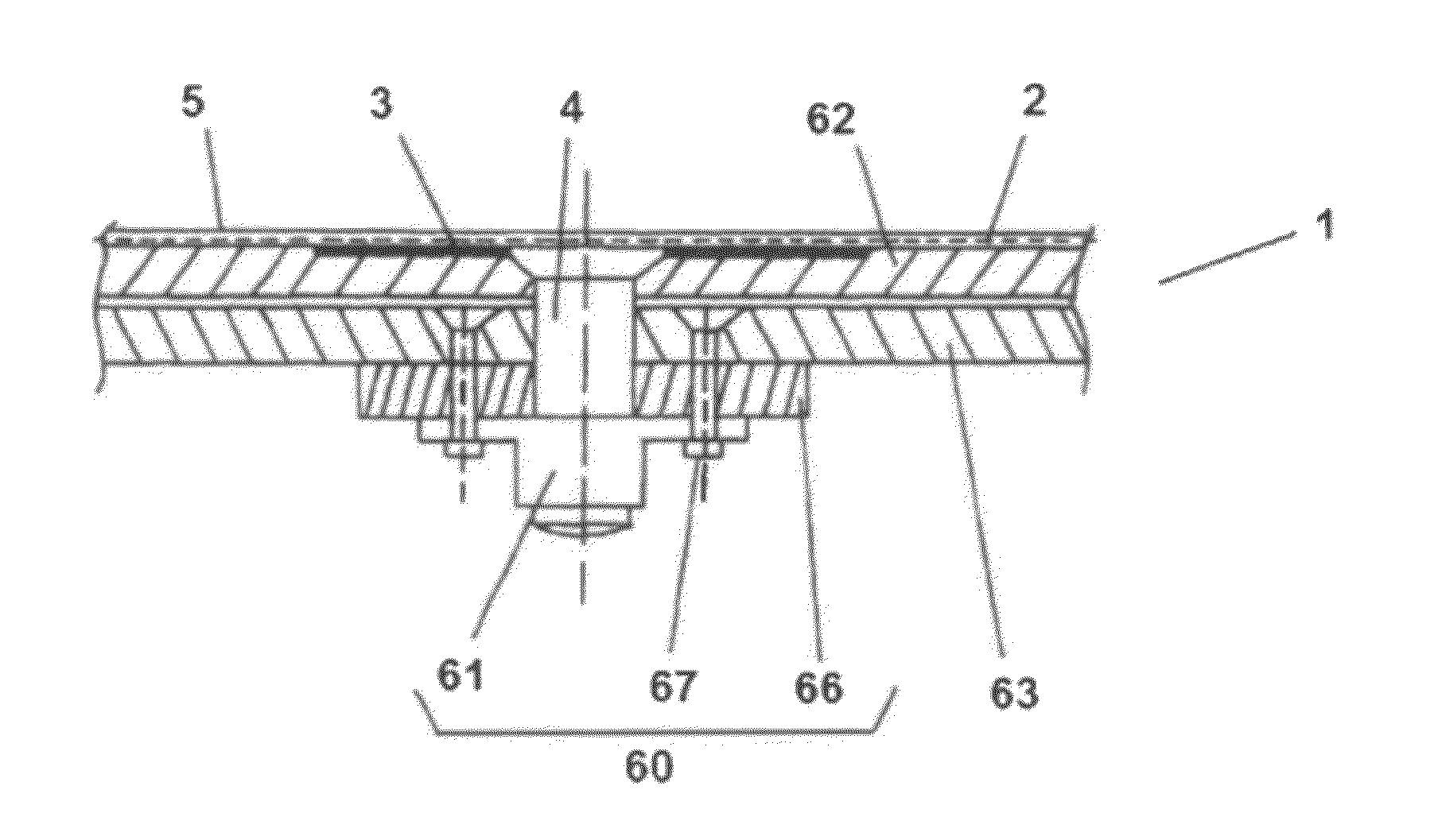
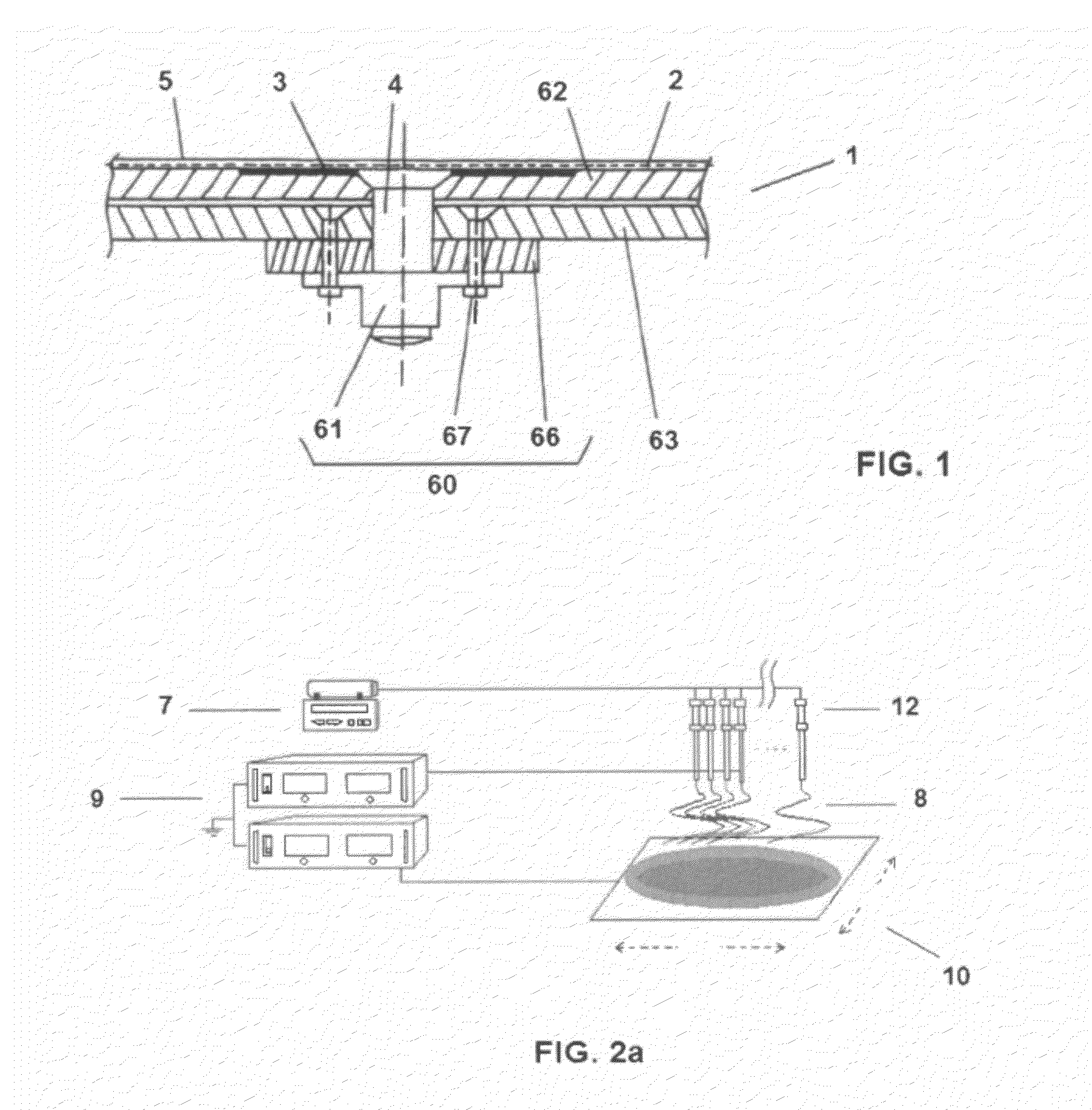
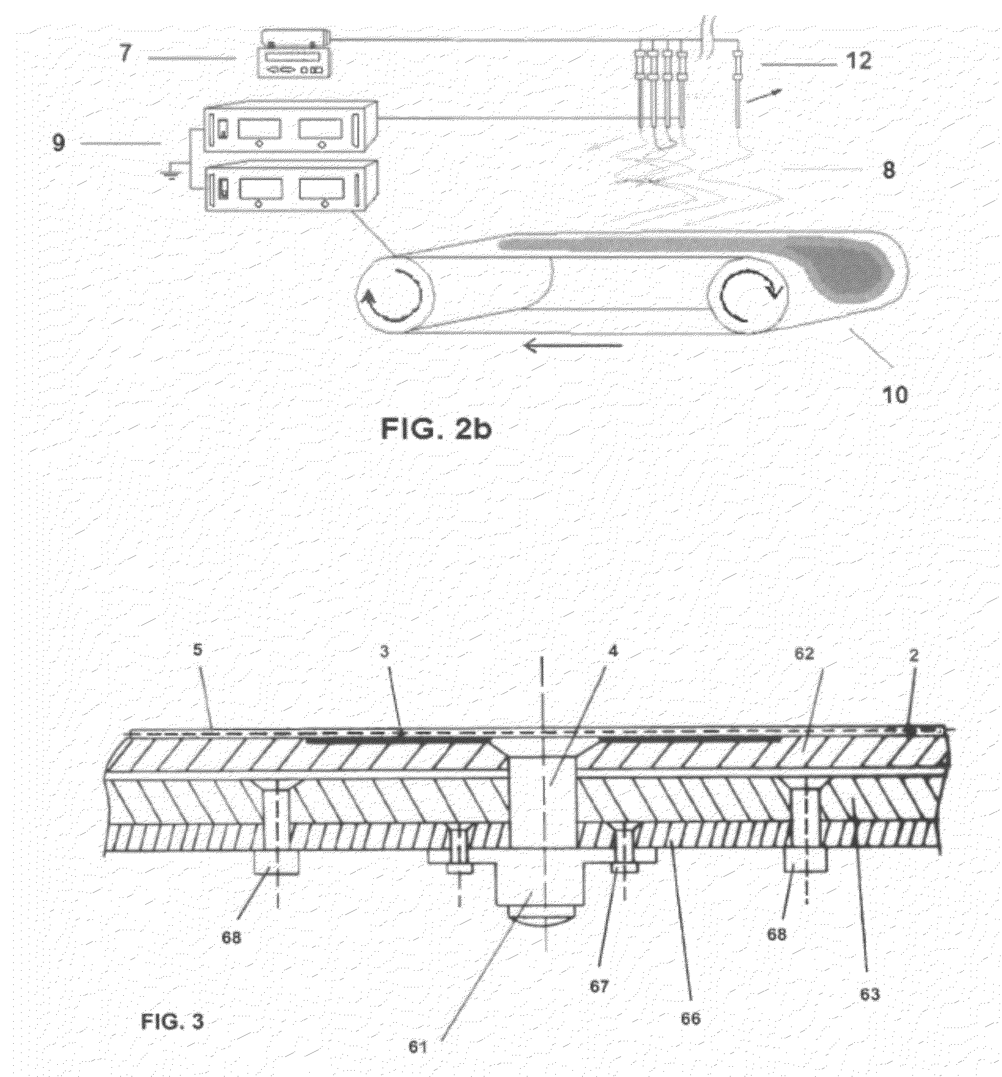
[0018]Thus, the invention refers to a lightning protection system 1 for aircraft structures comprising a composite material and forming a fuel tank or enclosing ignitable vapours, in particular in the joint of structures 62, 63. The system 1 of the invention aims at providing lightning protection to the areas surrounding a fastening element 4, such that the fastening element 4 attaches an internal structure 63 to an external structure 62 of the aircraft.

[0019]The lightning protection system 1 of the invention comprises at least one conductive layer 2 or 3 embedded in the matrix of the composite material forming the aircraft structure, in proximity to a fastening element 4. The lightning protection system 1 may comprise only one conductive layer 2, covering an area of the structure for which lightning protection is sought, this layer 2 comprising conductive nanoparticles dispersed within its structure, such that the properties of this layer 2 against lightning are improved. In anothe...


PUM


Abstract

Lightning protection system (1) for aircraft structures, comprising a fastening element (4) for attaching an internal structure (63) to an external structure (62), and a composite material providing lightning protection to areas surrounding the fastening element (4), the lightning protection system (1) comprising at least one conductive layer (2, 3) embedded in the matrix of said composite material and in proximity to the fastening element (4), the conductive layer (2, 3) comprising conductive nanoparticles dispersed within its structure.

Description

FIELD OF THE INVENTION[0001]The invention relates to a lightning protection system for aircraft structures comprising a composite material, in particular in the joints of aircraft structures forming a fuel tank or enclosing ignitable vapours.BACKGROUND[0002]At present, because of the massive use of composite materials in aircraft structures, and due to the low values of both the electrical and thermal conductivities of said composite materials when compared to conventional metallic structures, together with the high electrical resistance at the structural joints in aircraft structures made of these materials, sparking becomes a frequent phenomenon as a consequence of the lightning current passage through these structures, especially in cases where the composite materials form part of aircraft structures forming a fuel tank or enclosing ignitable vapours. Phenomena such as sparking or hot spot, which may be produced by a lightning strike on the aircraft structure, are especially dang...

Claims


Application Information

Patent Timeline
Patent Type & Authority Applications(United States)
IPC IPC(8): B64D45/02
CPCB64D45/02
Inventor SEQUEIROS MURCIANO, FELIPECANO PEREZ, FERNANDOQUERO LOPEZ, MARIA VINAS
Owner EADS CONSTRS AERONAUTICAS
Why Eureka
Try Eureka