Electronic device

a technology of electronic devices and speakers, applied in the direction of piezoelectric/electrostrictive transducers, transducer types, contacts, etc., can solve the problems of not emitted sound generated in the speaker unit cannot be satisfactorily emitted outside from the device case, etc., and achieve the effect of thinning the devi

Active Publication Date: 2012-05-24
CASIO COMPUTER CO LTD
View PDF3 Cites 10 Cited by
  • Summary
  • Abstract
  • Description
  • Claims
  • Application Information

AI Technical Summary

Benefits of technology

[0011]An object of the present invention is to provide an electronic device having a mounting structure for a speaker which is simple and by which the thinning of the device can be achieved and sound generated by the speaker can be satisfactorily emitted outside the device case.
[0013]In the present invention, the speaker can be easily attached by simply being fitted in the speaker attaching section provided on the contact sheet arranged on the circuit board inside the case. Accordingly, the structure is simple and the number of its components is small, whereby the thickness of the device can be reduced. In addition, sound generated by the speaker can be favorably emitted outside the case without chattering noise being generated.

Problems solved by technology

However, there is a problem in this conventional mounting structure for a speaker in that the thickness from the front surface of the key top to the undersurface of the speaker unit is large and therefore the thinning of the device cannot be achieved.
In addition, there is another problem in this conventional mounting structure for a speaker in that sound generated in the speaker unit cannot be satisfactorily emitted outside from the device case.
Although a mounting structure has been developed in which the contact sheet between the speaker unit and the key sheet is arranged underneath the speaker unit, and the speaker unit is placed closer to the key tops of the key sheet, there is a problem in that sound generated in the speaker unit is not emitted from only the sound emitting hole in the key top because it leaks to the surrounding area of the speaker unit.
Accordingly, the contact sheet is required to be provided on or underneath the speaker unit, and therefore the overall thickness cannot be made sufficiently thin.

Method used


Image

  • Electronic device
  • Electronic device
  • Electronic device

Examples


Embodiment Construction

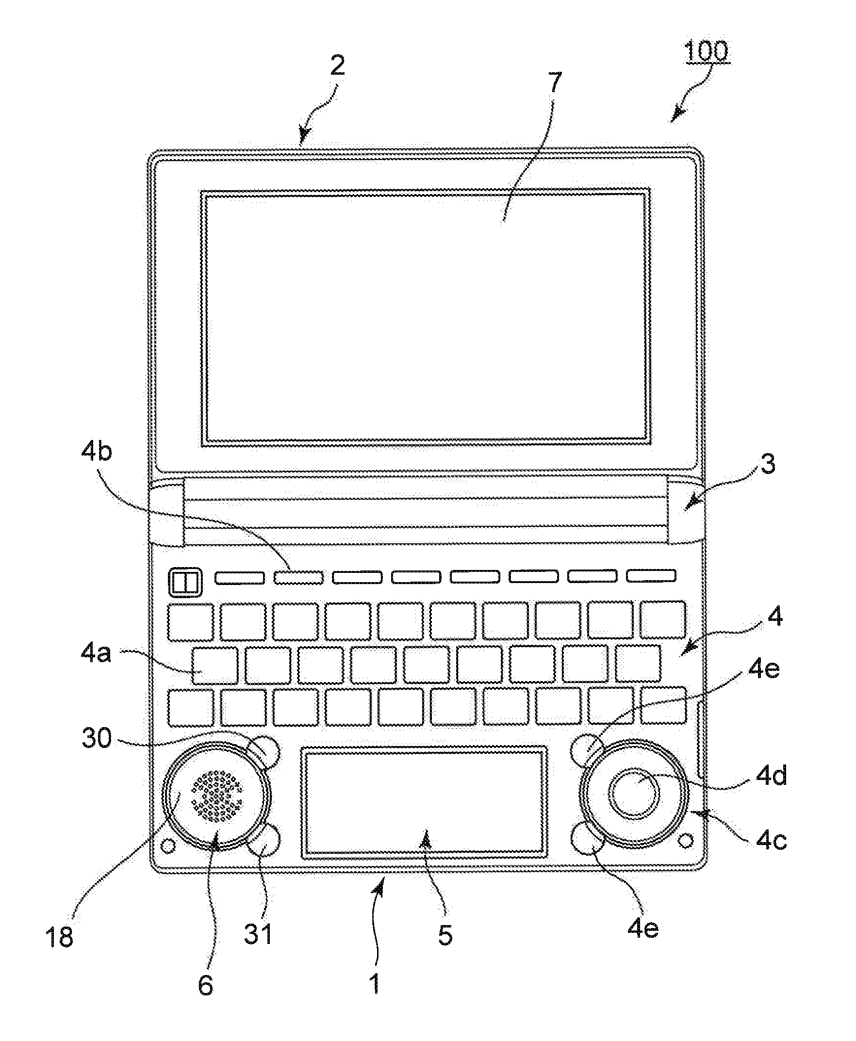
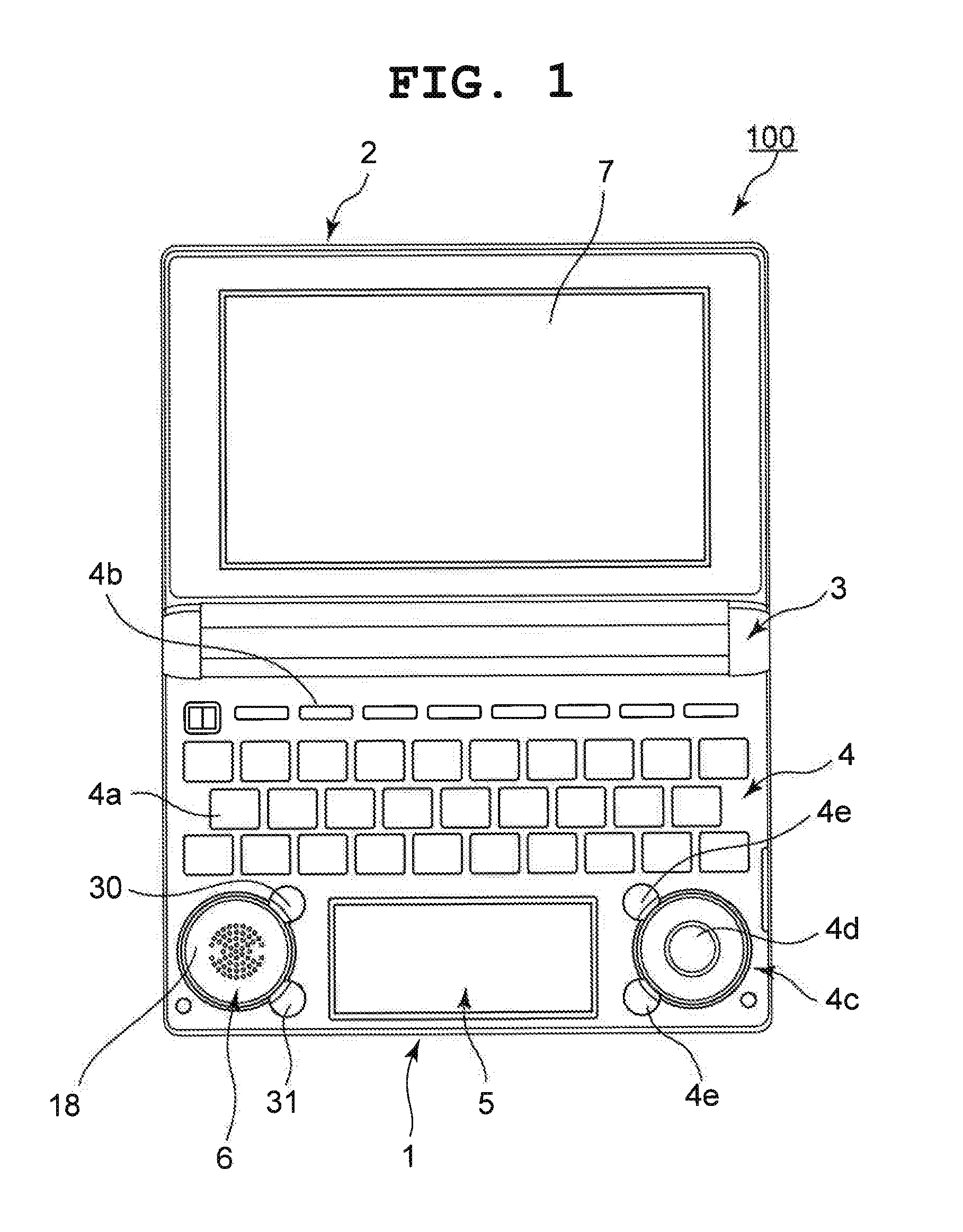
[0031]An embodiment in which the present invention has been applied to an electronic dictionary will hereinafter be described with reference to FIG. 1 to FIG. 15.

[0032]As shown in FIG. 1, an electronic dictionary 100 is structured such that a first case 1 and a second case 2 are openably and closably connected by a hinge section 3.

[0033]The first case 1 includes a key input section 4, a touch input section 5, and a speaker section 6, and the second case 2 includes a display section 7. The display section 7 is constituted by a flat display panel such as a liquid crystal display panel or an electroluminescent (EL) display panel, and electro-optically displays various information required for a dictionary function.

[0034]The key input section 4 includes various keys required for the dictionary function, such as character keys 4a, function keys 4b, and a cursor key 4c. In this instance, an enter key 4d is provided in the center of the cursor key 4c, and two auxiliary keys 4e are provided...


PUM


Abstract

In an electronic device, a speaker attaching section 17 which is vertically open with respect to a circuit board 10 and into which a speaker 16 is press-fitted is integrally formed on a contact sheet 13 arranged on the circuit board 10 provided inside an upper case 8. Therefore, the speaker 16 can be easily attached in a manner that sound therefrom does not leak, simply by the speaker 16 being press-fitted into the speaker attaching section 17 of the contact sheet 13. Accordingly, in the present invention, the structure of the speaker section 6 is simple and the number of its components is small, whereby the thickness of the speaker section 6 can be reduced. In addition, sound generated by the speaker can be favorably and reliably emitted from the speaker attaching section 17 to the outside of the upper case 8, without chattering noise being generated.

Description

CROSS-REFERENCE TO RELATED APPLICATION[0001]This application is based upon and claims the benefit of priority from the prior Japanese Patent Application No. 2010-261018, filed Nov. 24, 2010, the entire contents of which is incorporated herein by reference.BACKGROUND OF THE INVENTION[0002]1. Field of the Invention[0003]The present invention relates to an electronic device including a speaker, such as an electronic dictionary, a mobile phone, or a personal digital assistant (PDA).[0004]2. Description of the Related Art[0005]As a mounting structure for a speaker in a mobile phone, a structure is known in which a speaker unit is provided on a circuit board inside a device case, a contact sheet having a plurality of contact sections is provided on the circuit board, a key sheet having a plurality of key tops is provided on the contact sheet and each key top of the key sheet is exposed from the surface of the device case, as described in Japanese Patent Application Laid-Open (Kokai) Publi...

Claims


Application Information

Patent Timeline
Patent Type & Authority Applications(United States)
IPC IPC(8): H04R1/02
CPCH04R2499/15H04R1/2896
Inventor WATANABE, KIYOSHIMAEDA, MAKI
Owner CASIO COMPUTER CO LTD
Why Eureka
Try Eureka