Supercharge Your Innovation With Domain-Expert AI Agents!

Vortex Enhanced Wind Turbine Diffuser

a wind turbine and diffuser technology, applied in the direction of wind turbines, motors, liquid fuel engines, etc., can solve the problems of thickness and hence strength

Inactive Publication Date: 2012-05-24
KINETIC HARVEST
View PDF10 Cites 25 Cited by
  • Summary
  • Abstract
  • Description
  • Claims
  • Application Information

AI Technical Summary

Benefits of technology

[0013]A further object of this invention is for the diffuser to be able to be manufactured from low cost materials using low cost processes.
[0050]By being able to tilt vertically it can better utilise the rising wind streams you would find on hills and escarpments, precisely where the wind is the strongest.

Problems solved by technology

Also the size of a diffuser determines its wind loading which being proportional to the cube of the wind speed becomes an issue in overload wind conditions.
This has construction issues as the reduced chord of the diffuser rings also reduces their thickness and hence strength, and yet they must be attached in a sufficiently robust way to sustain the requisite peak loads.

Method used


Image

  • Vortex Enhanced Wind Turbine Diffuser
  • Vortex Enhanced Wind Turbine Diffuser
  • Vortex Enhanced Wind Turbine Diffuser

Examples


Embodiment Construction

[0064]In the drawings, preferred embodiments of the invention are illustrated by way of example. The description and drawings are only for the purpose of illustration and preferred designs, and are not intended as a definition of the limits of the invention.
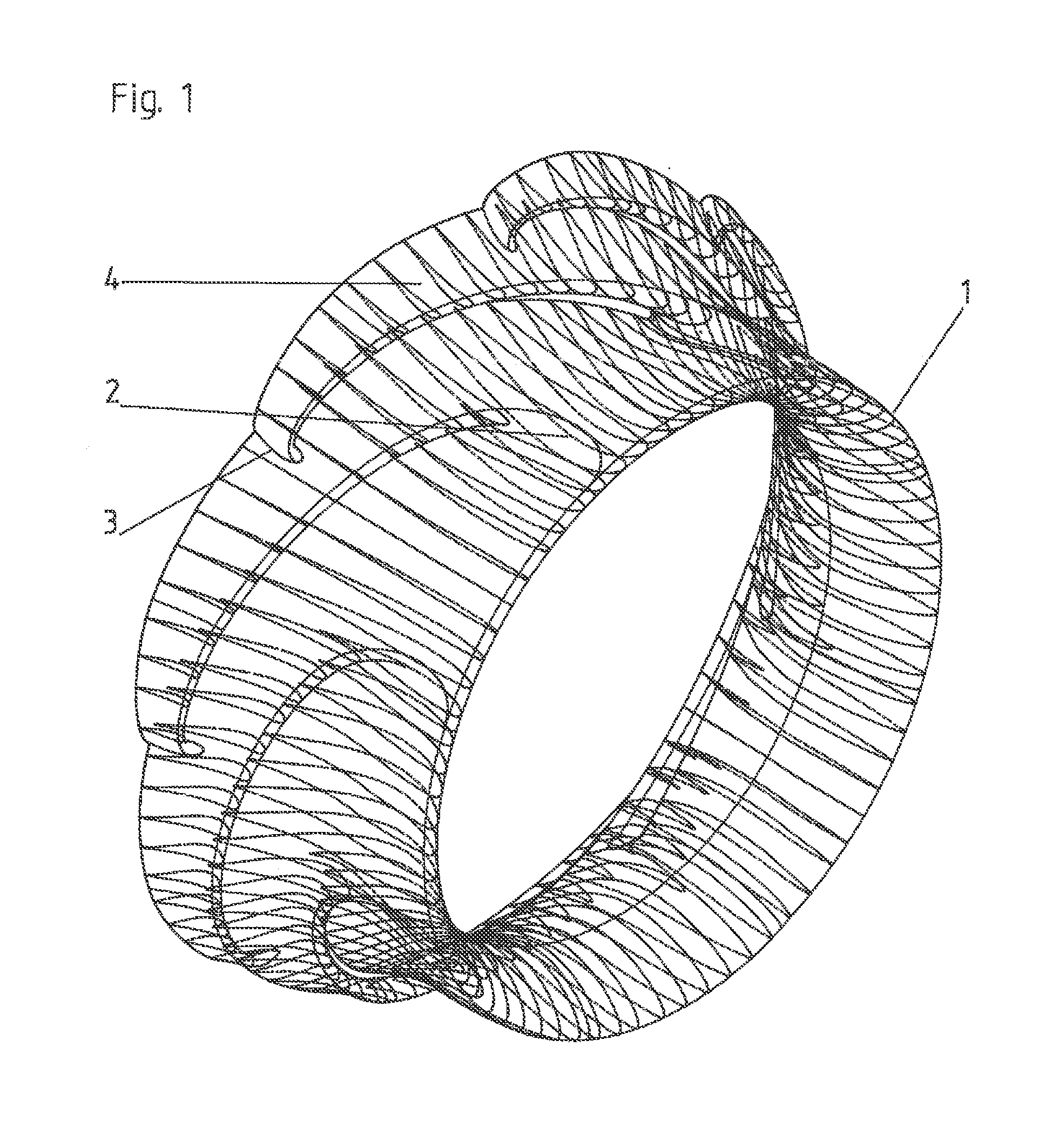
[0065]In FIG. 1

[0066]An embodiment of the invention is shown where the duct leading edge (1) blends radially with an increasing chord and thickness up to the transition point (2) where the winglet (4) breaks away to extend out and back until it can attach to the neighboring winglet (3).
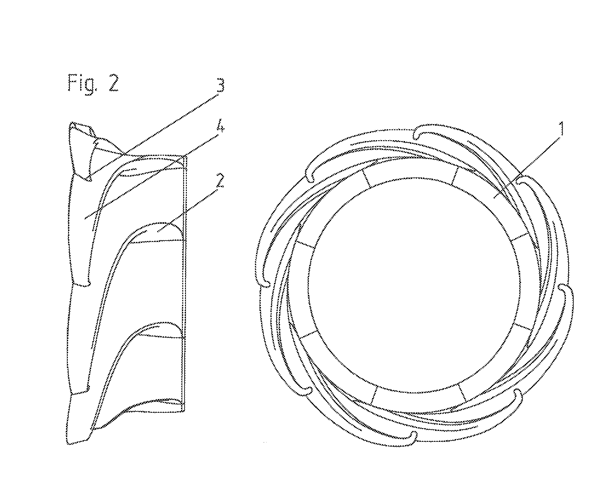
[0067]In FIG. 2

[0068]The same embodiment is shown at a side elevation and a front elevation illustrating where the segments join.
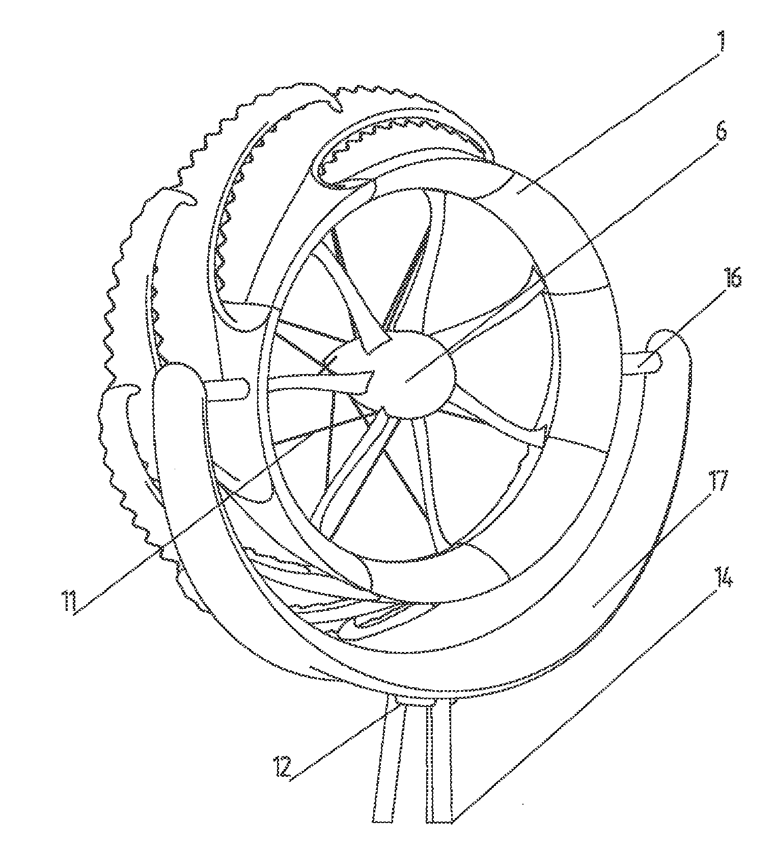
[0069]In FIG. 3

[0070]An embodiment with a convoluted trailing edge (5) is shown that acts to promote the mixing of low and high energy flow through the venturi effect. The power pod (6) is mounted in the centre of the duct, with external struts e.g. (7) connecting to the segments to provide a rigid mounting means to the t...


PUM


Abstract

A diffuser for a wind turbine where slots in said diffuser wall entrain air to enter into the diffuser with a swirl that is counter to the internal swirl created as a reaction to the turbine blades rotation as it extracts power such that the internal swirl and the externally introduced swirl cross over each other thereby causing vortices to form between them that energizes the internal flow and helps to prevent it from separating from the internal duct wall. Such a diffuser would beneficially consist of a radial array of repeated segments each comprising a radial portion of a duct with a wing emerging from behind said duct leading edge and spiraling out and backwards and connecting back onto the wing of the next segment round such that each segment's wing connects to the trailing neighboring segment wing just as the leading neighbors wing connects onto it, and that a gap is left between the spiral arms to permit external air to flow between the trailing edge of one segment wing and the leading edge of the adjacent wing.

Description

FIELD OF THE INVENTION[0001]The present application pertains to a novel compact diffuser for enhancing the pressure differential across a turbine blade set to thereby extract more power for a given turbine diameter.[0002]The present invention relates to the use of an aerodynamic cowling that entrains air flow into a duct, increasing the pressure ahead of the turbine blades and a diffuser to generate low pressure behind the turbine blades, thereby increasing the pressure differential. Such a device is optimized for effectiveness at a minimum size and to achieve maximum robustness.BACKGROUND OF THE INVENTION[0003]Diffuser Augmented Wind Turbines (DAWTs) are well known and understood. They first emerged in the 1970s when several patents were granted for both small and large scale devices.[0004]A diffuser will accelerate the wind through the turbine, and as power is proportional to wind speed cubed, the use of a diffuser enables smaller diameter blades to achieve the same power yield. I...

Claims


Application Information

Patent Timeline
IPC IPC(8): F03D11/00
CPCF03D1/04F05B2240/122F05B2240/13Y02E10/72F05B2250/15F05B2250/25F05B2250/5011F05B2240/133F03D13/20
Inventor BAILEY, RALPH-PETER
Owner KINETIC HARVEST
Features
  • R&D
  • Intellectual Property
  • Life Sciences
  • Materials
  • Tech Scout
  • Unparalleled Data Quality
  • Higher Quality Content
  • 60% Fewer Hallucinations
Learn More