
Tabbed connector interface

a connector interface and tabbed technology, applied in the direction of coupling device connection, coupling device details, coupling/disengagement of coupling parts, etc., can solve the problems of increasing the time and effort required to make an interconnection, affecting the electrical performance of an entire rf system, and creating an unacceptable impedance discontinuity

Active Publication Date: 2012-05-24
COMMSCOPE TECH LLC
View PDF7 Cites 50 Cited by
  • Summary
  • Abstract
  • Description
  • Claims
  • Application Information

AI Technical Summary

Benefits of technology

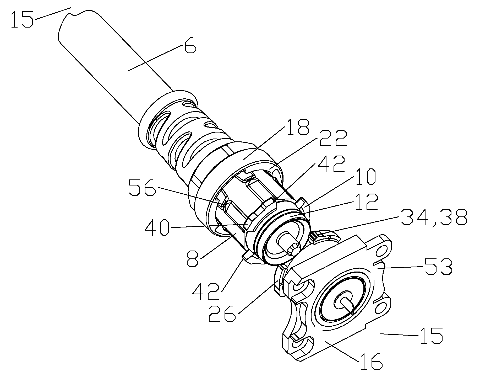
[0041]The cable end 15 of the base tabs 26 and / or coupling tabs 22 may be provided with an angled engagement surface 52 (see FIG. 11) for ease of initial engagement therebetween. Thereby, as the lock ring 18 is rotated, the coupling tab 22 is driven against the angled engagement surface 52 and the coupling tab 22 is progressively drawn toward the cable end 15 as the coupling tab 22 advances along the engagement surface 52, driving the male portion 8 into engagement with the female portion 16.
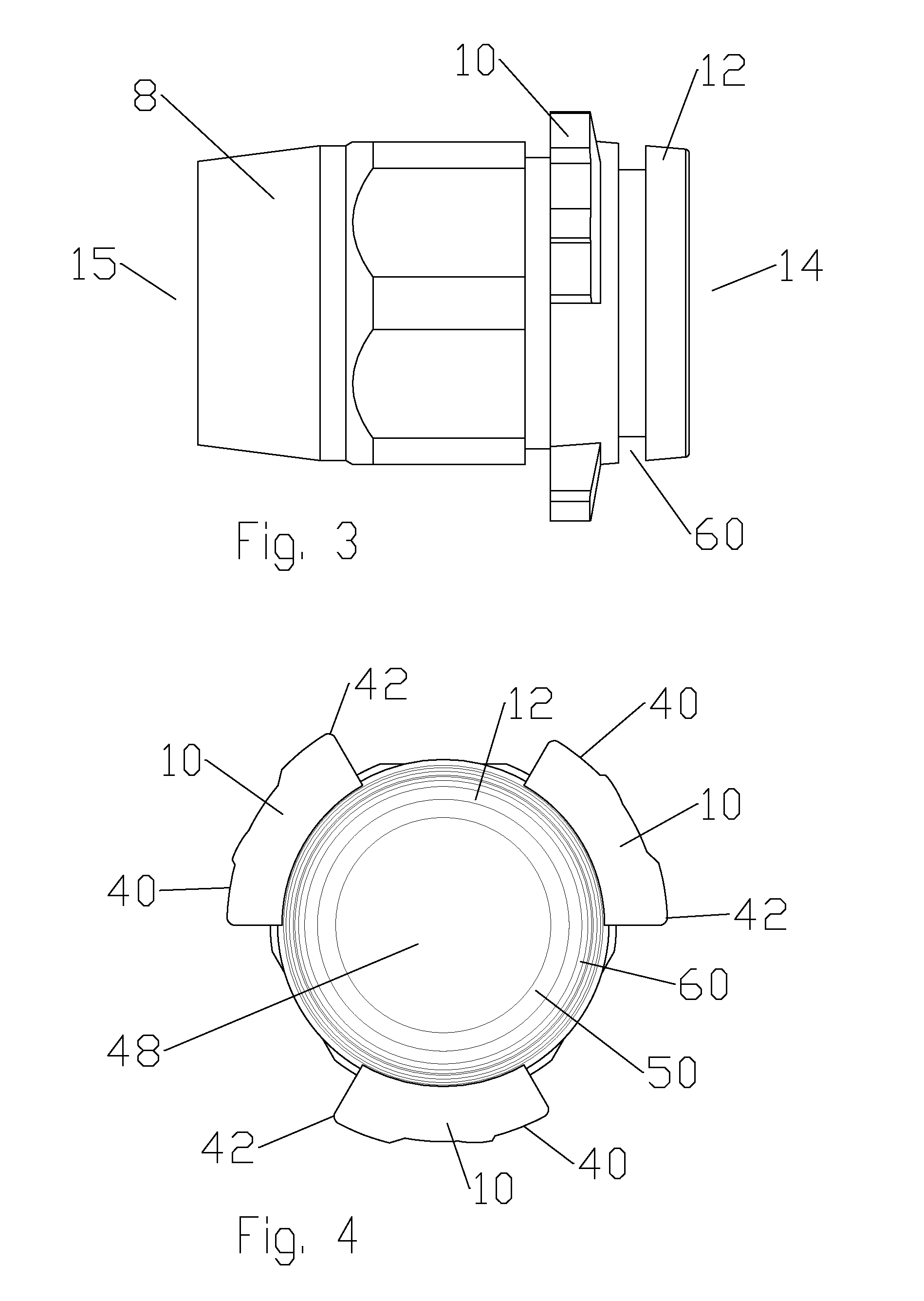
[0071]One skilled in the art will further appreciate that the tabbed connector interface provides a quick connect rigid interconnection with a reduced number of discrete elements, which may simplify manufacturing and / or assembly requirements. Contrary to conventional connection interfaces featuring threads, the conical aspect of the seat surface 12 is generally self-aligning, allowing interconnection to be initiated without precise initial male to female portion 8, 16 alignment along the longitudinal axis.Table of Parts2wrench4connector6cable8male portion10connector tab12seat surface14interface end15cable end16female portion18lock ring20stop shoulder22coupling tab24tab seat26base tab28annular groove30outer sidewall32tab seat lock34base tab lock36inward protrusion38outward protrusion40insertion surface42stop surface44outer conductor46inner sidewall48bore50flare surface52engagement surface53mounting flange54retention lip56retention spur58overbody60seal groove62seal

Problems solved by technology

Where connectors are mounted in high density / close proximity to one another and / or nearby obstructions, rotating the coupling nut during threading to advance the mating portions of the connection interface may be frustrated by the adjacent objects and / or associated cables, requiring frequent resetting of the rotation tool, which increases the time and effort required to make an interconnection.
As such, a BNC-type connection interface is not designed to support larger diameter and / or heavier coaxial cables and / or may create an unacceptable impedance discontinuity when utilized with a larger diameter coaxial cable.
PIM is an important interconnection quality characteristic as PIM from a single low quality interconnection may degrade the electrical performance of an entire RF system.

Method used


Image

  • Tabbed connector interface
  • Tabbed connector interface
  • Tabbed connector interface

Examples


Embodiment Construction

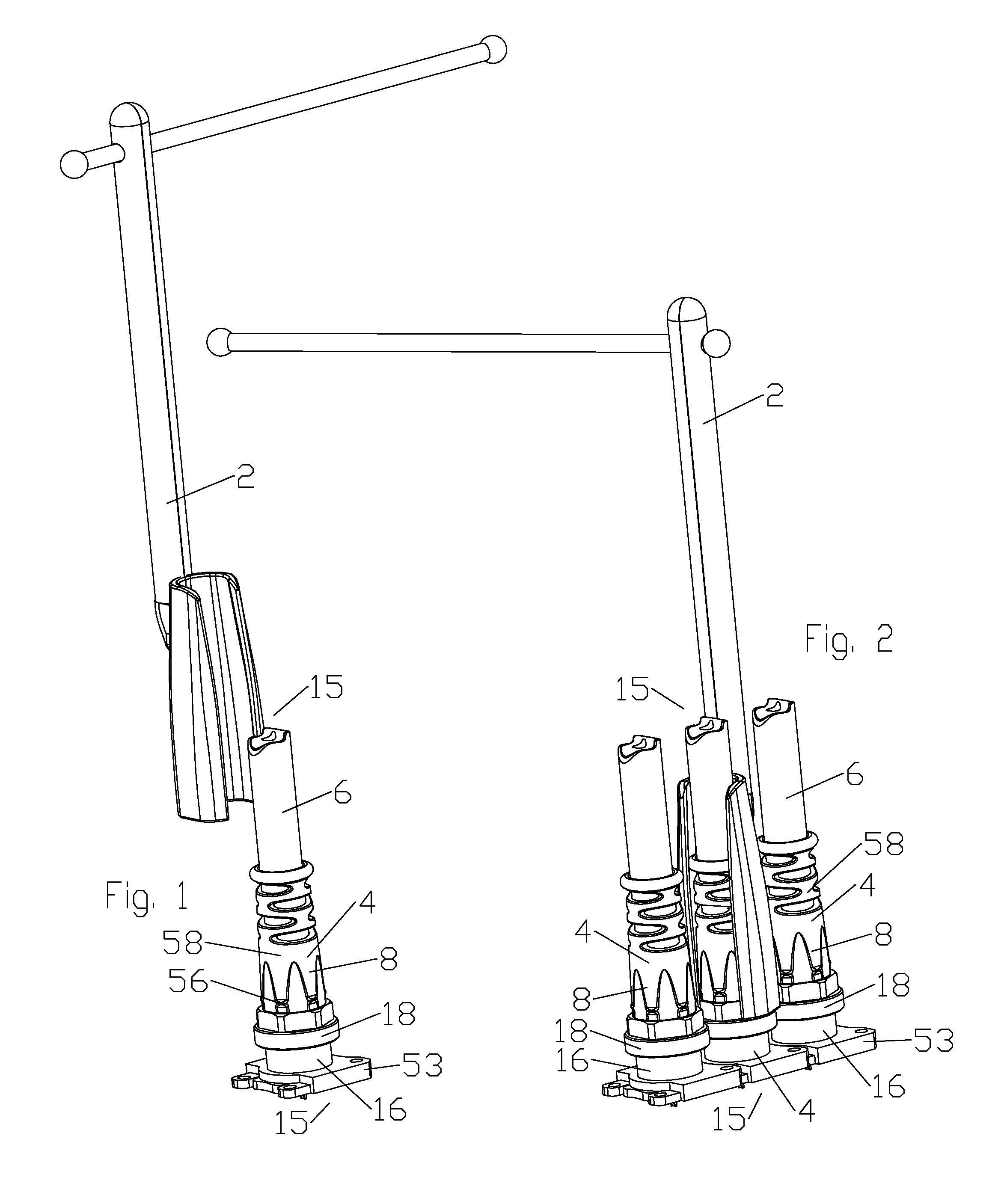
[0030]The inventor has recognized that threaded interconnection interfaces are particularly difficult to connect in high density / close proximity connector situations as a basin-type wrench 2 is required to access the connector 4, the wrench handle spaced away from the connector 4 along the longitudinal axis of the connector 4, for example as shown in FIGS. 1 and 2. Although it is possible to thread the connector bodies / coupling nuts together, starting the threading is difficult as the access to control how the connector bodies are aligning / seating together is frustrated and the repeated rotation required during the threading typically interferes with the cable 6 extending from the connector 4 and / or the cables 6 of adjacent connectors 4. Further, even where smaller diameter cables 6 are utilized, standard quick connection interfaces such as BNC-type interconnections may provide unsatisfactory electrical performance with respect to PIM, as the connector body may pivot laterally along...


PUM

PropertyMeasurementUnit
diameteraaaaaaaaaa
degree rotation engagementaaaaaaaaaa
outer diameteraaaaaaaaaa

Abstract

An electrical connector interface has a male portion and a female portion. The male portion provided with at least three outer diameter radial projecting connector tabs and a conical outer diameter seat surface at an interface end. A lock ring provided with a stop shoulder and at least three radial inward coupling tabs at the interface end seats around the male portion, the stop shoulder abutting the connector tabs, a tab seat provided between the coupling tabs and the stop shoulder. The female portion provided with at least three outer diameter radial projecting base tabs and an annular groove open to the interface end with an outer sidewall dimensioned to mate with the conical outer diameter seat surface. The base tabs engage the coupling tabs when the lock ring is rotated to insert the base tabs into the tab seat, retaining the outer diameter seat surface against the outer sidewall.

Description

CROSS REFERENCE TO RELATED APPLICATIONS[0001]This application is a continuation-in-part of commonly owned co-pending U.S. Utility patent application Ser. No. 13 / 277,611, titled “Close Proximity Panel Mount Connectors” filed Oct. 20, 2011 by Kendrick Van Swearingen. This application is a continuation-in-part of commonly owned co-pending U.S. Utility patent application Ser. No. 13 / 240,344, titled “Connector and Coaxial Cable with Molecular Bond Interconnection” filed Sep. 22, 2011 by Kendrick Van Swearingen and James P. Fleming. This application is also a continuation-in-part of commonly owned co-pending U.S. Utility patent application Ser. No. 13 / 170,958, titled “Method and Apparatus For Radial Ultrasonic Welding Interconnected Coaxial Connector” filed Jun. 28, 2011 by Kendrick Van Swearingen. This application is also continuation-in-part of commonly owned co-pending U.S. Utility patent application Ser. No. 13 / 161,326, titled “Method and Apparatus for Coaxial Ultrasonic Welding Inter...

Claims


Application Information

Patent Timeline
Patent Type & Authority Applications(United States)
IPC IPC(8): H01R13/213H01R43/00
CPCH01R9/05H01R13/625H01R13/6392Y10T29/49194H01R24/40H01R2103/00H01R43/20H01R13/64
Inventor VAN SWEARINGEN, KENDRICK
Owner COMMSCOPE TECH LLC
Learn More