Positioning apparatus and method for a prosthetic implant

a prosthetic implant and positioning apparatus technology, applied in the field of positioning apparatus and method of prosthetic implants, can solve the problems of reduced precision of traditional multi-use osteotomy templates, inconvenient operation, and difficulty for surgeons to determine the precise location of this osteotomy

Active Publication Date: 2012-05-24
THE CLEVELAND CLINIC FOUND
View PDF1 Cites 239 Cited by
  • Summary
  • Abstract
  • Description
  • Claims
  • Application Information

AI Technical Summary

Problems solved by technology

In patients with deformity associated with arthritis, the anatomic neck may be difficult to define, making it difficult for the surgeon to determine to precise location of this osteotomy.
Since traditional osteotomy templates are not adapted to the individual patient, they require the patients to have relatively similar anatomical characteristics.
This means that for patients with anatomical deviations, there is a reduction in precision with traditional multi-use osteotomy templates, thereby giving a final result that is not optimal.
For patients with greater anatomical deviations, moreover, the majority of multi-use templates will be difficult to use on account of limitations in the possibilities for adjustment.
Even for patients without great deviations, when using multi-use templates it will be necessary to carry out adjustments of the osteotomy template during the operation, resulting in an increased risk of error, increased operating time and thereby an increased risk of complications.

Method used


Image

  • Positioning apparatus and method for a prosthetic implant
  • Positioning apparatus and method for a prosthetic implant
  • Positioning apparatus and method for a prosthetic implant

Examples


Embodiment Construction

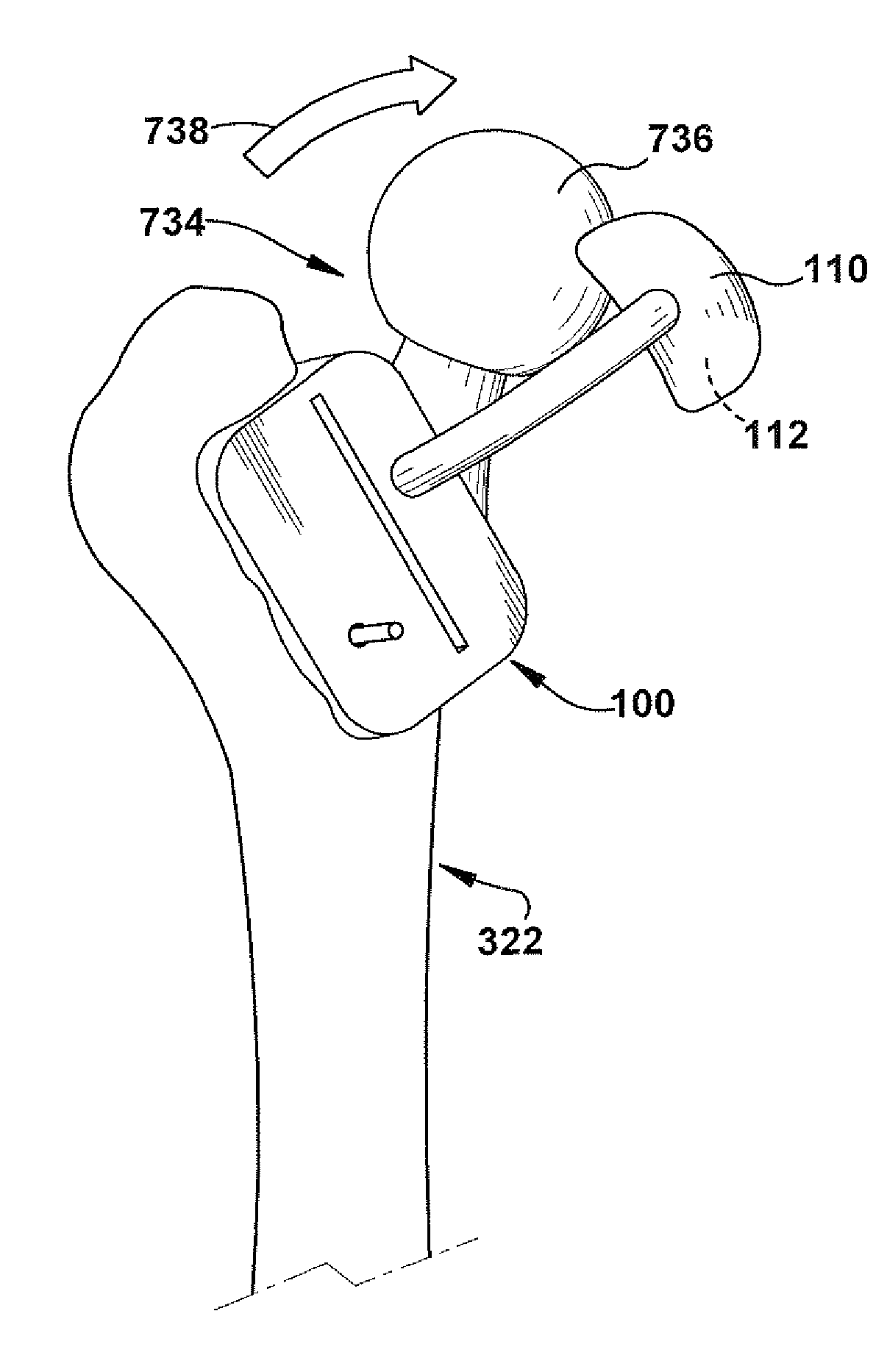
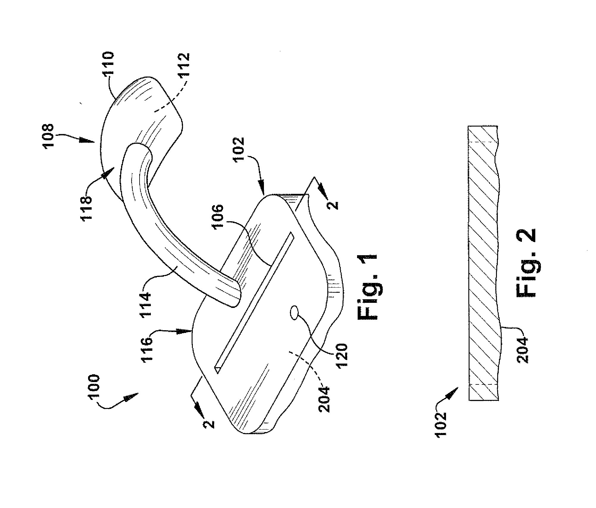
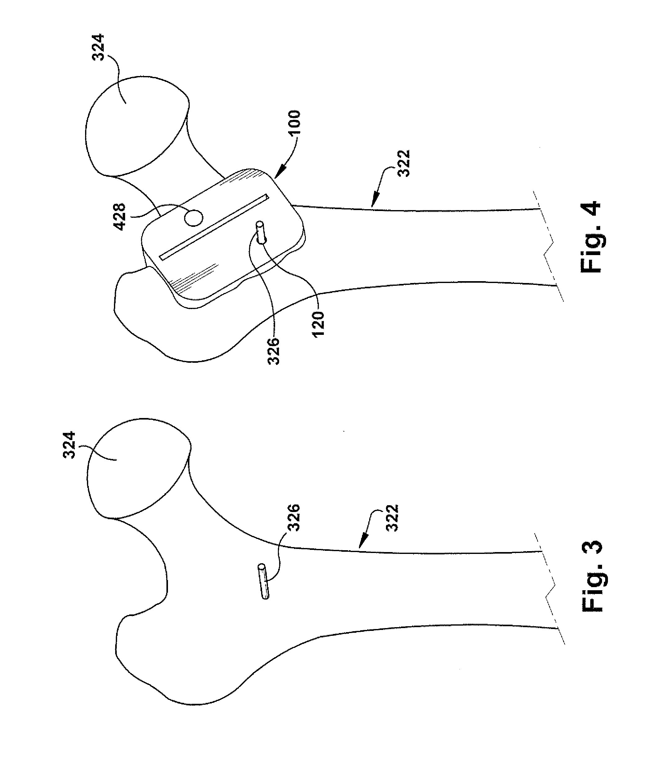
[0018]In accordance with the present invention, FIG. 1 depicts a schematic view of a positioning apparatus 100 for guiding resection of a patient tissue (not shown) and guiding placement of a prosthetic implant component (not shown) in a desired implant position with respect to the resected patient tissue. The patient tissue is shown and described herein as a femur and the prosthetic implant component is shown and described herein as a femoral prosthetic hip component, but the patient tissue and corresponding prosthetic implant component could be any desired types such as, but not limited to, hip joints, shoulder joints, knee joints, ankle joints, phalangeal joints, metatarsal joints, spinal structures, long bones (e.g., fracture sites), or any other suitable use environment for the present invention.

[0019]The positioning apparatus 100 includes a locating block 102. The locating block 102 includes a mating surface (204, shown in cross-section in FIG. 2), the mating surface being cus...


PUM


Abstract

A positioning apparatus for guiding resection of a patient tissue and guiding placement of a prosthetic implant component in a desired implant position with respect to the resected patient tissue and method of use are described. A locating block includes a mating surface contoured for mating contact with the patient tissue. A cutting plane indicator provides a physical indication of a desired cutting plane for the resection. A placement indicator is spaced apart from the locating block and includes a component-contacting feature. An elongate spacing arm is operative to space the placement indicator apart from the locating block. The spacing arm is configured to place the component-contacting feature of the placement indicator at a predetermined placement position in three-dimensional space relative to the patient tissue. The placement position predetermination is at least partially based upon pre-operative imaging of the patient tissue.

Description

RELATED APPLICATION[0001]This application claims priority from U.S. Provisional Application No. 61 / 380,476, filed Sep. 7, 2010, the subject matter of which is incorporated herein by reference.TECHNICAL FIELD[0002]The present invention relates to a positioning apparatus and method for a prosthetic implant and, more particularly, to a method and apparatus for guiding resection of a patient tissue and guiding placement of a prosthetic implant component in a desired implant position with respect to the resected patient tissue.BACKGROUND OF THE INVENTION[0003]Minimally invasive surgery (“MIS”) is quickly becoming standard for the implantation of prosthetic components into a patient. For example, the use of an MIS hip replacement technique involves a skin incision of approximately 7 cm and is performed without the previously required laying-open of the patient's entire hip area. MIS techniques for joint replacement may reduce trauma to the patient, with less pain, less blood loss, shorter...

Claims


Application Information

Patent Timeline
Patent Type & Authority Applications(United States)
IPC IPC(8): A61B17/56
CPCA61B17/15A61B2017/568A61B2019/507A61B2019/508A61F2/4603A61F2002/30542A61F2002/4687A61B17/17A61F2/4607A61B2034/107A61B2034/108A61F2002/3054
Inventor IANNOTTI, JOSEPH P.BARSOUM, WAEL K.BRYAN, JASON A.
Owner THE CLEVELAND CLINIC FOUND
Why Eureka
Try Eureka