Pump having stepper motor and overdrive control

a stepper motor and control technology, applied in the direction of mechanical equipment, machines/engines, transportation and packaging, etc., can solve the problems of lubricant becoming stiff or thick, and achieve the effect of reducing viscosity, easy flow, and improving efficiency

Active Publication Date: 2012-05-31
LINCOLN INDUSTRIES CORP
View PDF8 Cites 34 Cited by
  • Summary
  • Abstract
  • Description
  • Claims
  • Application Information

AI Technical Summary

Benefits of technology

[0007]In one aspect the present invention is directed to an apparatus for pumping lubricant that includes a reservoir having an interior for holding lubricant. The apparatus also includes a stirrer rotatable in the reservoir. One advantage of the stirrer includes maintaining the lubricant at a viscosity sufficiently low that the lubricant more easily flows. In colder environmental conditions, the lubricant may become stiff or thick. The stirrer fluidizes the lubricant which allows the lubricant pump to operate more efficiently. The apparatus further includes a force-feed mechanism on the stirrer operable on rotation of the stirrer to exert a pushing force pushing lubricant from the reservoir along a defined flow path. The apparatus also includes a pump below the reservoi

Problems solved by technology

In colder environmental conditions, th

Method used


Image

  • Pump having stepper motor and overdrive control
  • Pump having stepper motor and overdrive control
  • Pump having stepper motor and overdrive control

Examples


Embodiment Construction

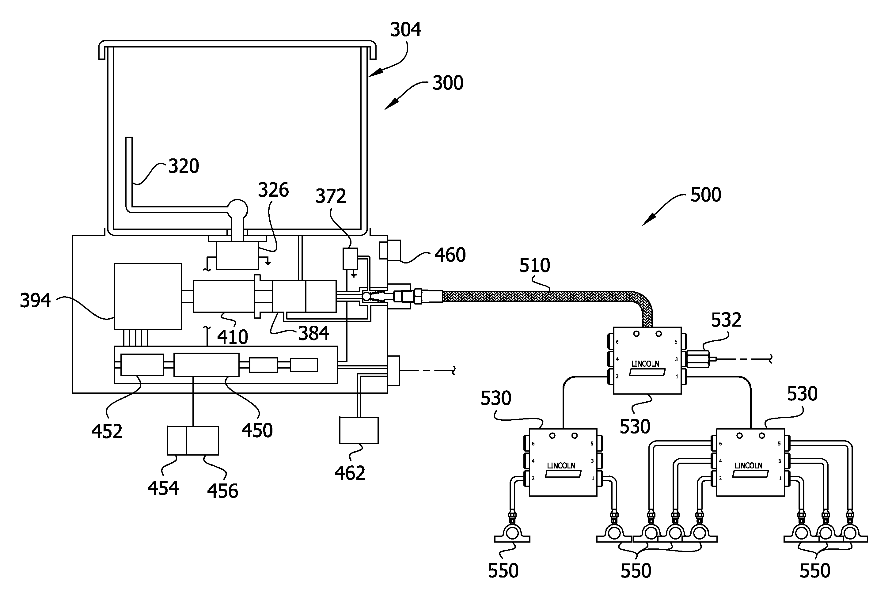
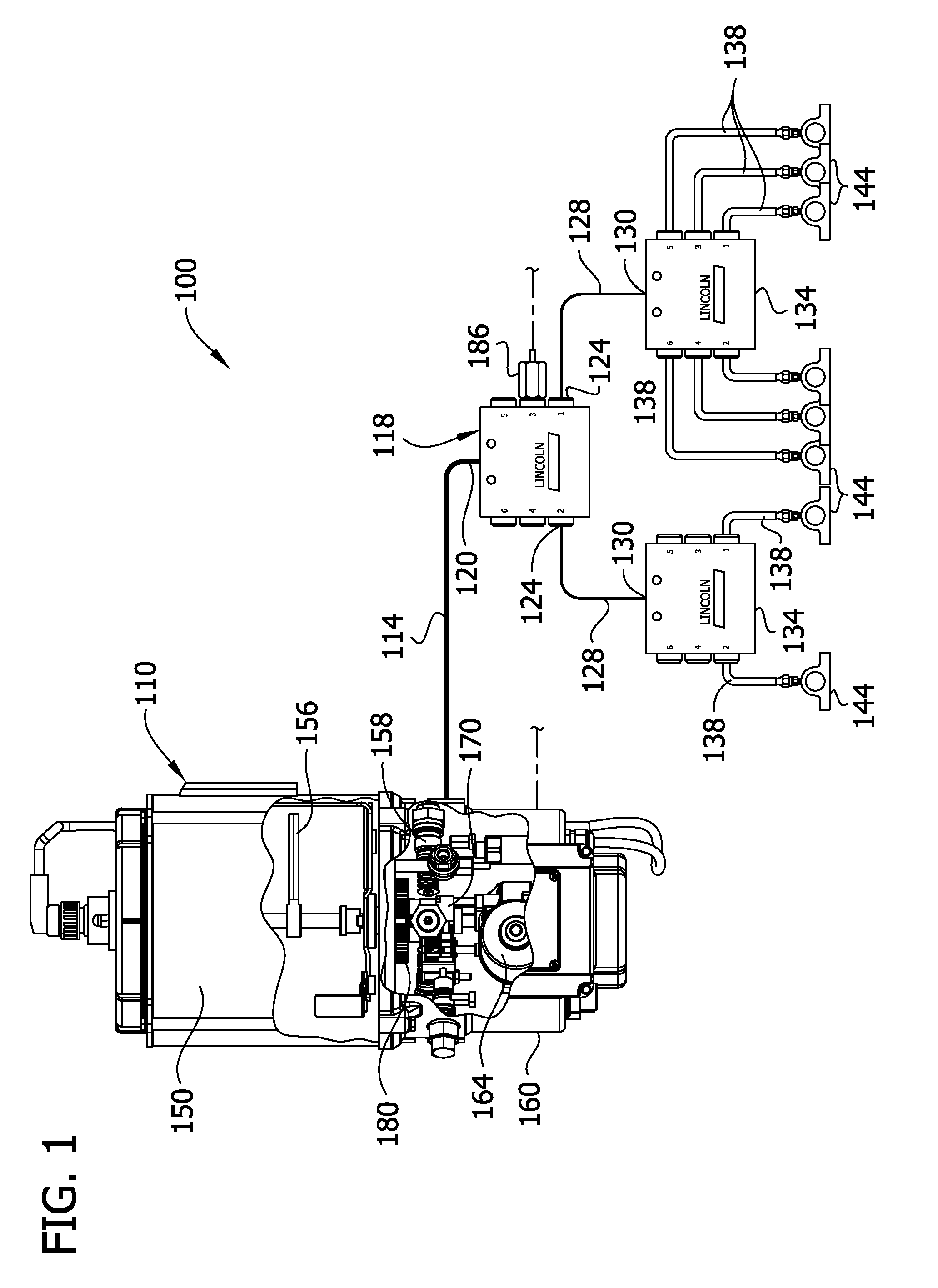
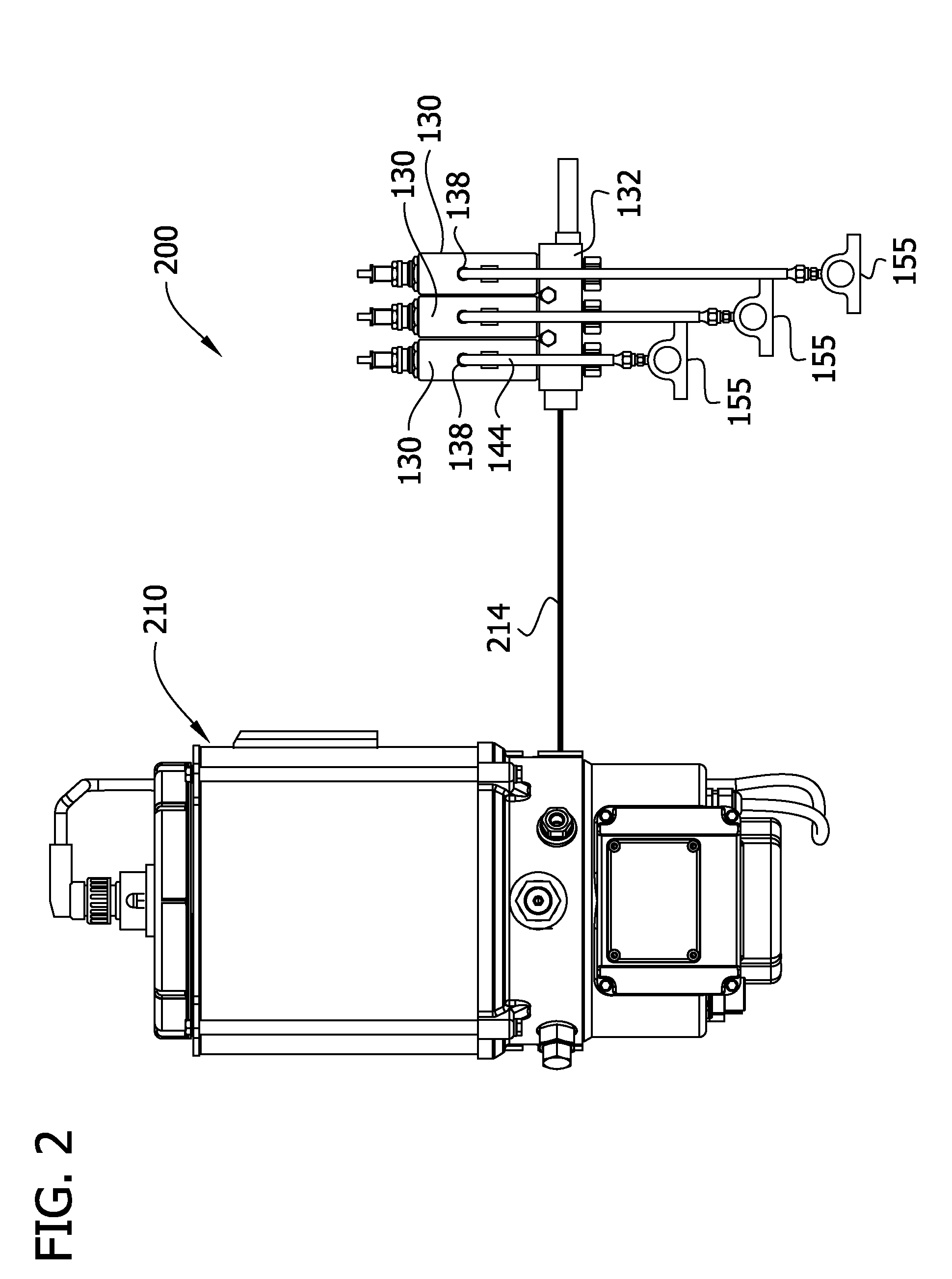
[0084]FIG. 1 illustrates a conventional Quicklub® system, generally designated 100, comprising a pump unit 110 that operates to pump lubricant through a lube supply line 114 to a master divider valve, generally designated by 118, having an inlet 120 and multiple outlets 124 connected via lines 128 to the inlets 130 of additional (slave) divider valves, generally designated by 134. The divider valves 134 are connected via lines 138 to bearings 144 or other points of lubrication. The number of divider valves 134 used will vary depending on the number of lubrication points to be serviced.

[0085]The pump unit 110 includes a reservoir 150 for holding a lubricant (e.g., grease), a stirrer 156 for stirring the lubricant in the reservoir, and an expansible chamber pump 158 in a pump housing 160 below the reservoir. A motor 164 in the pump housing rotates the stirrer 156 to stir lubricant in the reservoir. The motor also 164 rotates an eccentric mechanism 170 to move a spring-biased piston th...


PUM


Abstract

Apparatus and method for supplying lubricant to a plurality of lubrication sites. Embodiments include a pump with venting and non-venting piston return, a pump with stirrer and direct feed mechanism, a pump with CAN system and self-diagnostics, a pump with heated housing and reservoir and a pump with stepper motor and overdrive control.

Description

CROSS REFERENCE TO RELATED APPLICATION[0001]The present application claims priority to and benefit of U.S. Provisional Patent Application 61 / 417,606, filed Nov. 29, 2010, entitled, “Application and Method for Supplying Lubricant”, and U.S. Provisional Patent Application 61 / 533,530, filed Sep. 12, 2011, entitled, “Application and Method for Pumping Lubricant”, both of which are incorporated by reference in their entireties.FIELD OF THE INVENTION[0002]The present invention generally relates to apparatus for supplying lubricant, and more particularly to an automatic lubrication system for automatically pumping lubricant to a plurality of lubrication sites.BACKGROUND OF THE INVENTION[0003]This invention has particular application to automatic lubrication systems for supplying lubricant to multiple points of lubrication at predetermined intervals and / or in predetermined amounts. Lincoln Industrial sells such automated systems under the Quicklub®, Centro-Matic® and Helios® trademarks. The...

Claims


Application Information

Patent Timeline
IPC IPC(8): F01M1/02F01M1/18F16N7/38
CPCF16N7/14F16N13/02F16N7/38Y10T137/86035F16N29/00F16N29/02F16N29/04F16N2270/70
Inventor CONLEY, PAUL G.BECK, DAVID C.DONOVAN, NATHAN D.
Owner LINCOLN INDUSTRIES CORP
Why Eureka
Try Eureka