Cross-flow filtration with turbulence and back-flushing action for use with online chemical monitors

a cross-flow filtration and back-flushing technology, applied in the field of filtration systems used, to achieve the effect of reducing the buildup of filter cak

Active Publication Date: 2012-05-31
BL TECH INC
View PDF6 Cites 12 Cited by
  • Summary
  • Abstract
  • Description
  • Claims
  • Application Information

AI Technical Summary

Benefits of technology

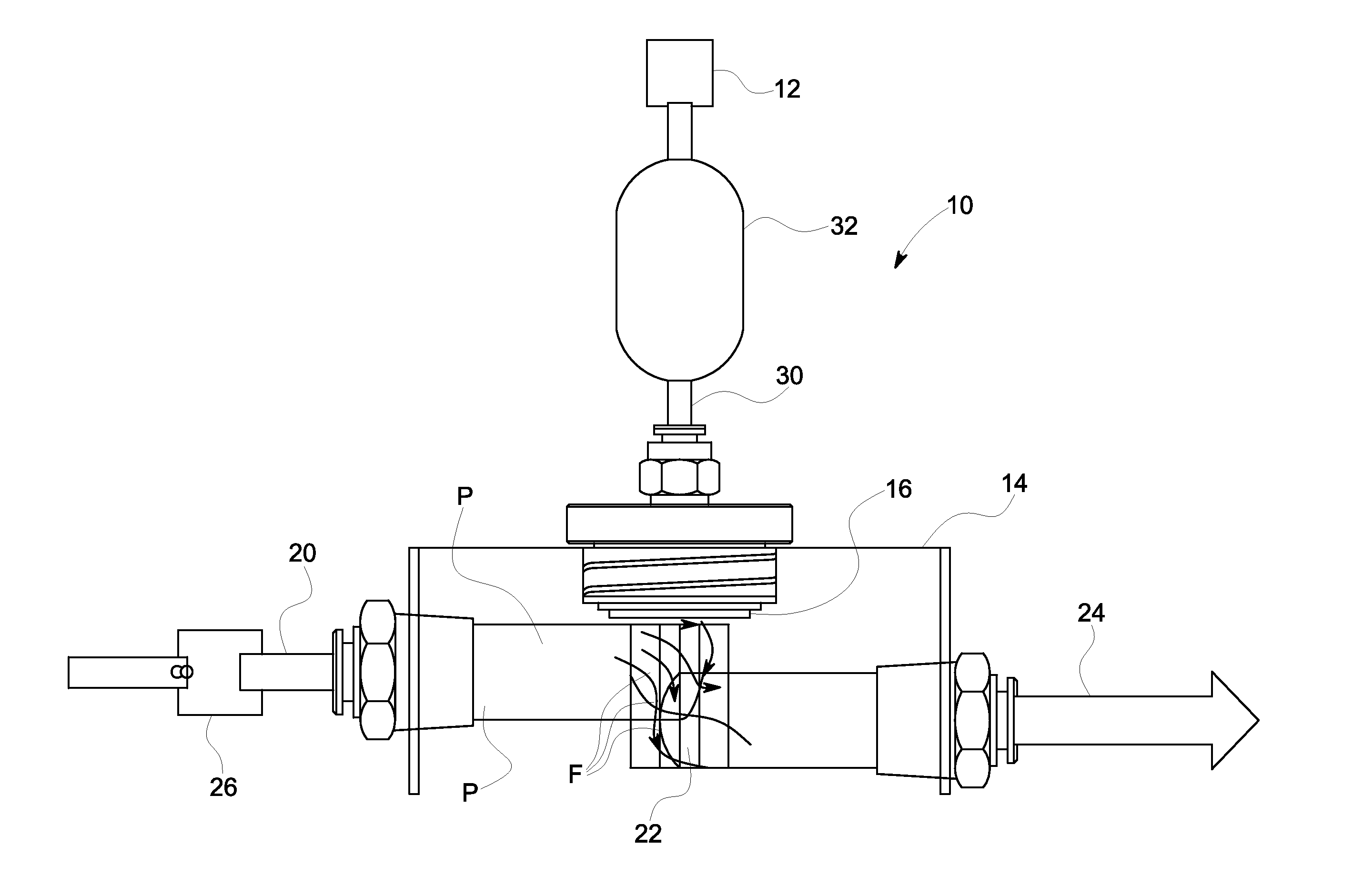
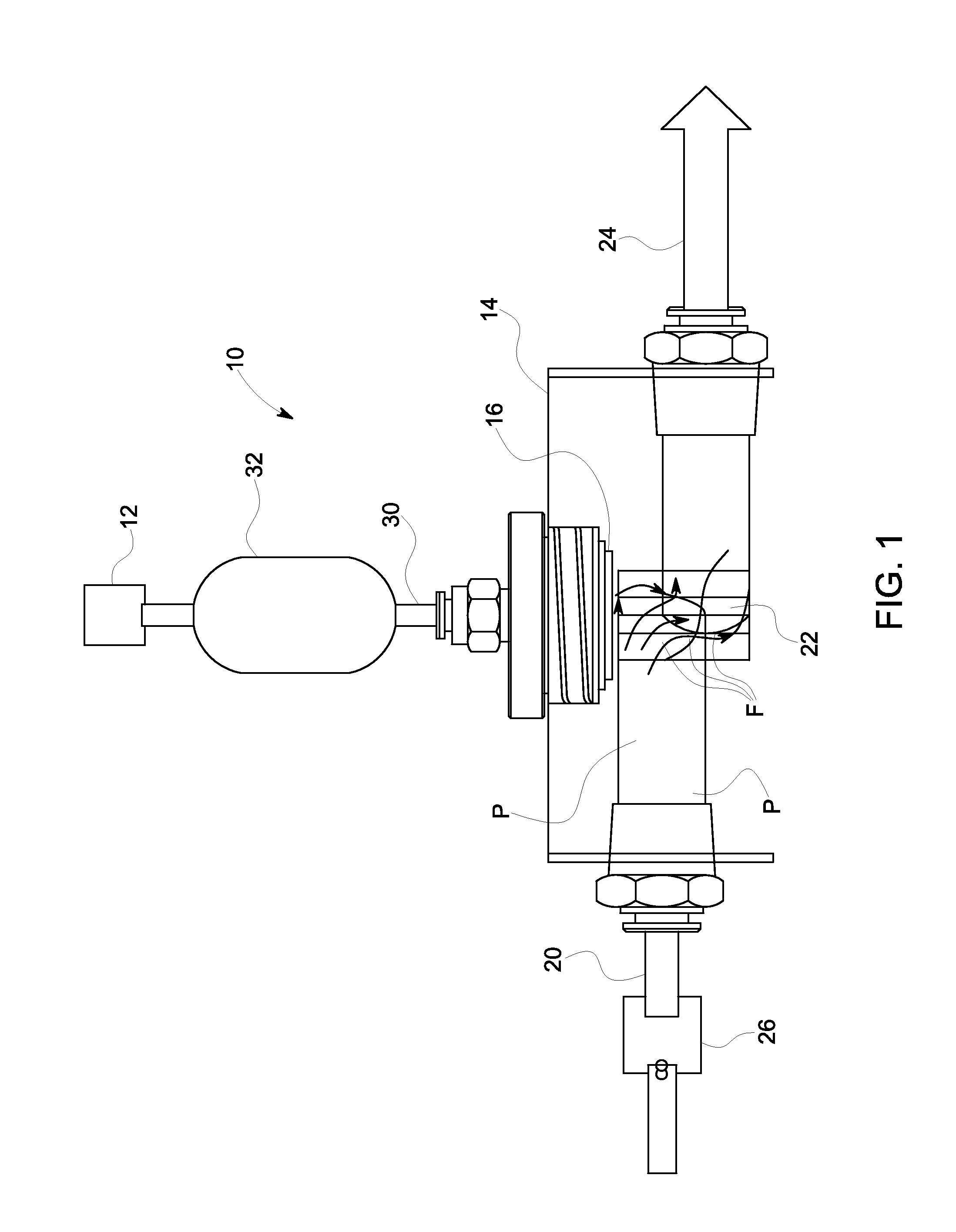
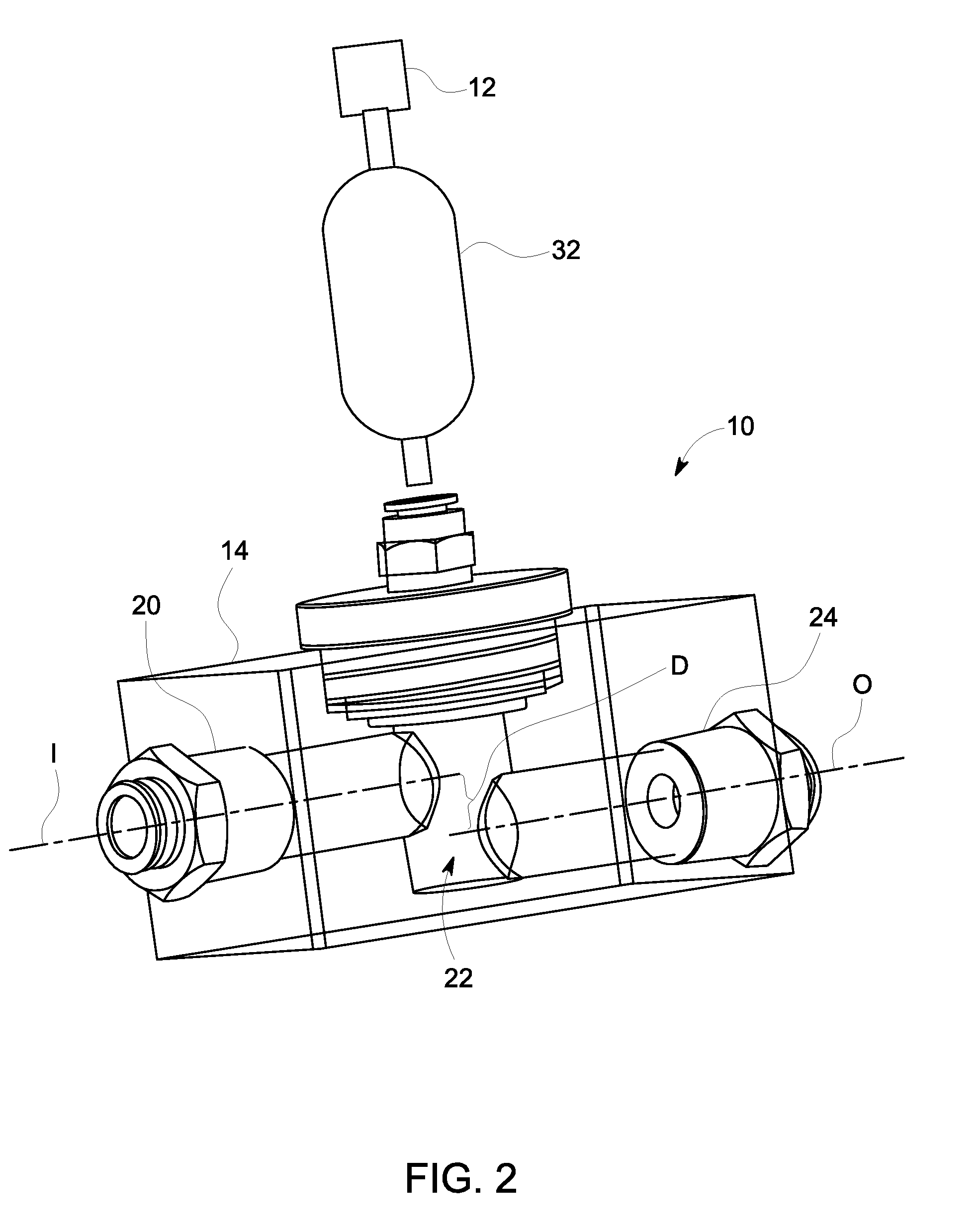
[0006]In one aspect, the invention is directed to a filtration and monitoring system for online monitoring of a parameter in a fluid system. The filtration and monitoring system includes an online monitoring device and a filter block forming a chamber therein and having a filter element. An inlet pipe provides fluid to the filter block chamber. The inlet pipe defines an inlet axis and further has an inlet valve located therein configured to shut off the flow of the fluid through the inlet pipe. An outlet pipe removes fluid from the filter block chamber, wherein the outlet pipe defines an outlet axis. A filtered fluid conduit fluidically connects the filter block with the monitoring device. The outlet axis of the outlet pipe is offset from the inlet axis of the inlet pipe such that the fluid undergoes a change of direction while passing through the filter block chamber thereby causing turbulent flow within the filter block chamber. The turbulent flow produces a cleaning vortex flow within the filter block that sweeps off particles that accumulate on the filter block chamber-side of the filter element to reduce the buildup of filter cake on the filter element. Closing the inlet valve causes a relatively sharp stop to the flow of fluid through the filter block resulting in a back-flushing flow of fluid from a pressure accumulator located in the filtered fluid conduit to the filter block chamber through the filter element. The back-flushing flow of fluid dislodges filter cake accumulated on the filter block chamber-side of the filter element.

Problems solved by technology

Unfortunately, the filter elements utilized to filter such fluids must be periodically replaced or cleansed to remove a clogging accumulation of contaminants and foreign matter therefrom.

Method used


Image

  • Cross-flow filtration with turbulence and back-flushing action for use with online chemical monitors
  • Cross-flow filtration with turbulence and back-flushing action for use with online chemical monitors
  • Cross-flow filtration with turbulence and back-flushing action for use with online chemical monitors

Examples


Embodiment Construction

[0013]The invention will now be described in the following detailed description with reference to the drawings, wherein preferred embodiments are described in detail to enable practice of the invention. Although the invention is described with reference to these specific preferred embodiments, it will be understood that the invention is not limited to these preferred embodiments. But to the contrary, the invention includes numerous alternatives, modifications, and equivalents as will become apparent from consideration of the following detailed description.

[0014]Referring to FIGS. 1 and 2, an online filtration system 10 used in conjunction with a chemical monitoring device for a fluid system such as an industrial cooling water system, boiler water system, waste water system, pulp paper water system, or other fluid system. Generally, the filtration system 10 is used with an online monitoring device 12 capable of monitoring a desired parameter of the fluid in the fluid system and a fil...


PUM

PropertyMeasurementUnit
pore sizeaaaaaaaaaa
pore sizeaaaaaaaaaa
distanceaaaaaaaaaa

Abstract

A filtration and monitoring system includes an online monitoring device and a filter block having a chamber therein. An inlet pipe provides fluid to the filter block chamber and has an inlet valve located therein configured to shut off the flow of the fluid through the inlet pipe. An outlet pipe removes fluid from the filter block chamber. A filtered fluid conduit fluidically connects the filter block with the monitoring device. The outlet axis of the outlet pipe is offset from the inlet axis of the inlet pipe such that the fluid undergoes a change of direction while passing through the filter block chamber thereby causing turbulent flow within the filter block chamber. The turbulent flow within the filter block sweeps off particles that accumulate on the filter block chamber-side of the filter element to reduce the buildup of filter cake on the filter element. Closing the inlet valve causes a relatively sharp stop to the flow of fluid through the filter block, resulting in a back-flushing flow of fluid through the filter element from a pressure accumulator located in the filtered fluid conduit to the filter block chamber. The back-flushing flow of fluid dislodges filter cake accumulated on the filter block chamber-side of the filter element.

Description

BACKGROUND OF THE INVENTION[0001]1. Field of the Invention[0002]The invention relates to filtration systems used with chemical monitoring systems and, more particularly, to a filtration system configured to use turbulent and reverse flow to remove contaminants from its filter element.[0003]2. Description of Related Art[0004]Chemical monitoring sensors often require a filtered supply of a coolant, lubricant, fuel, water or other fluid to be monitored to maintain the proper operation and maintenance of a multitude of industrial systems. Unfortunately, the filter elements utilized to filter such fluids must be periodically replaced or cleansed to remove a clogging accumulation of contaminants and foreign matter therefrom. The periodic removal and replacement of a clogged filter element generally requires the shutting down of the industrial system during the replacement procedure. The expensive, nonproductive downtime of the industrial system, the replacement cost of the filter element ...

Claims


Application Information

Patent Timeline
Patent Type & Authority Applications(United States)
IPC IPC(8): B01D29/62B01D29/00
CPCB01D29/66B01D29/908B01D29/904
Inventor BYALSKIY, MIKHAILLINK, BRIAN
Owner BL TECH INC
Why Eureka
Try Eureka