Fiber optic cable with improved low temperature and compression resistance

a fiber optic cable and compression resistance technology, applied in the field of communication cables, can solve the problems of limiting the free space in the tube, the failure of the cable eventually, and the increase of the situation, so as to achieve the effect of improving the cold temperature resistan

Active Publication Date: 2012-05-31
BERK TEK
View PDF3 Cites 17 Cited by
  • Summary
  • Abstract
  • Description
  • Claims
  • Application Information

AI Technical Summary

Benefits of technology

[0010]The present arrangement overcomes the drawbacks associated with the prior art and provides a loose tube fiber optic cable design for mid-count fiber optic...

Problems solved by technology

Although this design is adequate for many purposes it has certain drawbacks particularly with cold temperature resistance for designs having four (4) tubes because the center space is small relative to the cold temperature contraction forces of the tubes and jacket areas.
Thus, as the temperat...

Method used


Image

  • Fiber optic cable with improved low temperature and compression resistance
  • Fiber optic cable with improved low temperature and compression resistance
  • Fiber optic cable with improved low temperature and compression resistance

Examples


Embodiment Construction

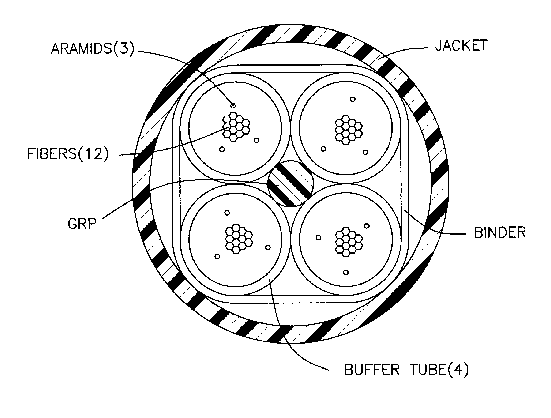
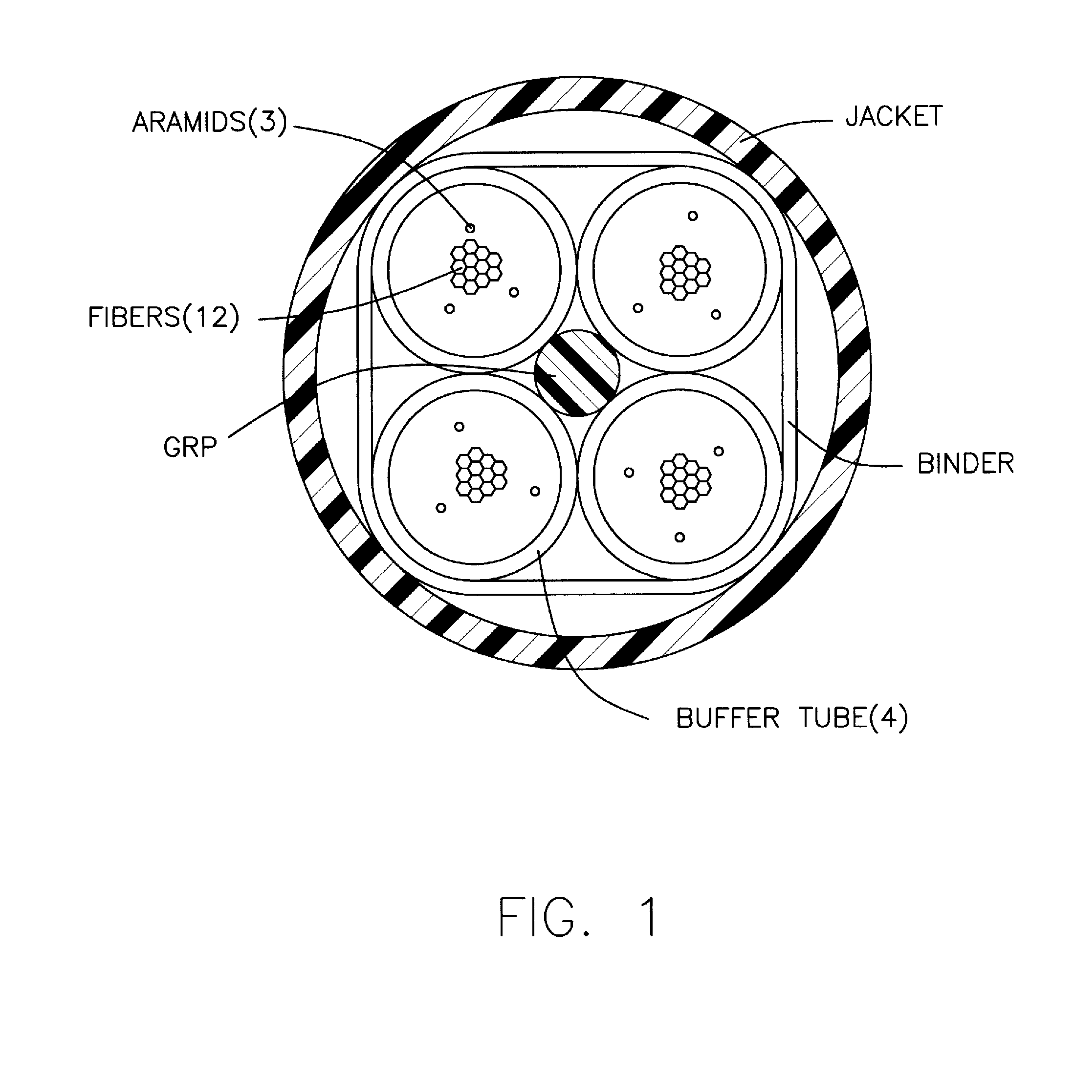
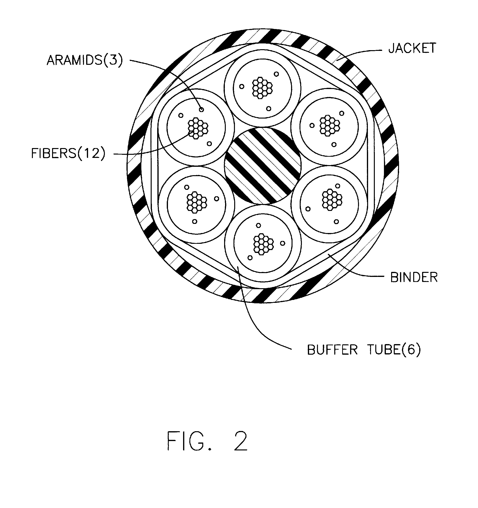
[0019]In one embodiment of the present arrangement shown in FIG. 3, a fiber optic cable 10 is shown for containing thirty six (36) fibers. Cable 10 includes an outer jacket 12 and three (3) buffer tubes 14 therein. Buffer tubes 14 are preferably constructed of FRPVC (Flame Resistant Polyvinylchloride), and jacket 12 is made from either PVDF (Polyvinylidene Fluoride) or FRPVC. It is noted that the invention is not limited in this respect and the features described herein for cable 10 may be used in cable construction using other polymers for jacket 12 and tubes 14 as desired.

[0020]Regarding the polymer used for jacket 12, PVDF provides very good smoke and fire resistance properties and also provide good crush resistance properties and cold temperature brittleness resistance. However, PVDF is expensive and does tend to have a higher coefficient of linear expansion / contraction meaning that in cold temperatures the PVDF jacket may shrink significantly (even more so than the FRPVC tubes)...


PUM


Abstract

A fiber optic cable is provided with a plurality of buffer tubes each with one or more optical fibers, a plurality of strength members and a jacket. The fibers within the cable meet maximum attenuation of substantially 0.07 db increase when decreasing from −23° C. to −60° C.

Description

BACKGROUND[0001]1. Field of the Invention[0002]This application relates to communication cables. More particularly, this application relates to loose-tube type fiber optic cables.[0003]2. Description of the Related Art[0004]In the area of fiber optic cables, there are many different designs, each of which has some purpose both in fiber count, mechanical properties, environmental resistance properties, fire resistance / smoke, etc . . . . Among the various designs, mid count-designs (eg. more than 12—less than 100 fibers) typically contain the fibers in a loose tube style arrangement. “Loose tube” is a commonly understood term designating a fiber cable design that has a jacket, at least one buffer tube inside the jacket with at least one (usually more) UV coated optical fiber(s) loosely contained inside each buffer tube.[0005]More particularly, the “loose” term in “loose tube” refers to the fibers being loose within buffer tube thus allowing the fibers to reside within a relatively fre...

Claims


Application Information

Patent Timeline
IPC IPC(8): G02B6/44
CPCG02B6/4413G02B6/4429
Inventor KELLER, DAVIDKROUSHL, PAULYODER, RANDIEROUSE, DAN
Owner BERK TEK
Why Eureka
Try Eureka