Conformal solid state package method and device for a battery device

a solid-state package and battery technology, applied in the field of electrochemical cell manufacturing, to achieve the effect of accurately encapsulating a battery device, optimizing battery energy density, and minimizing parasitic mass and volum

Inactive Publication Date: 2012-05-31
SAKTI3
View PDF2 Cites 24 Cited by
  • Summary
  • Abstract
  • Description
  • Claims
  • Application Information

AI Technical Summary

Benefits of technology

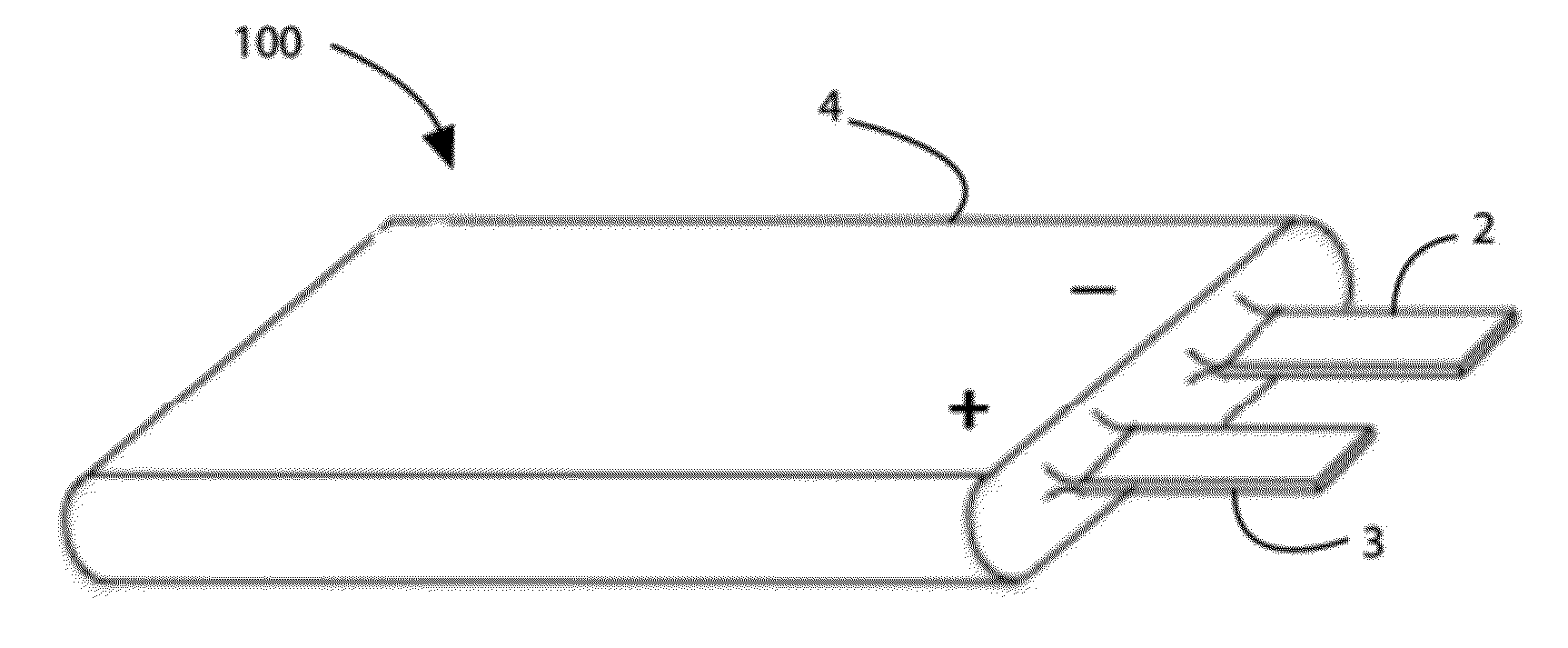
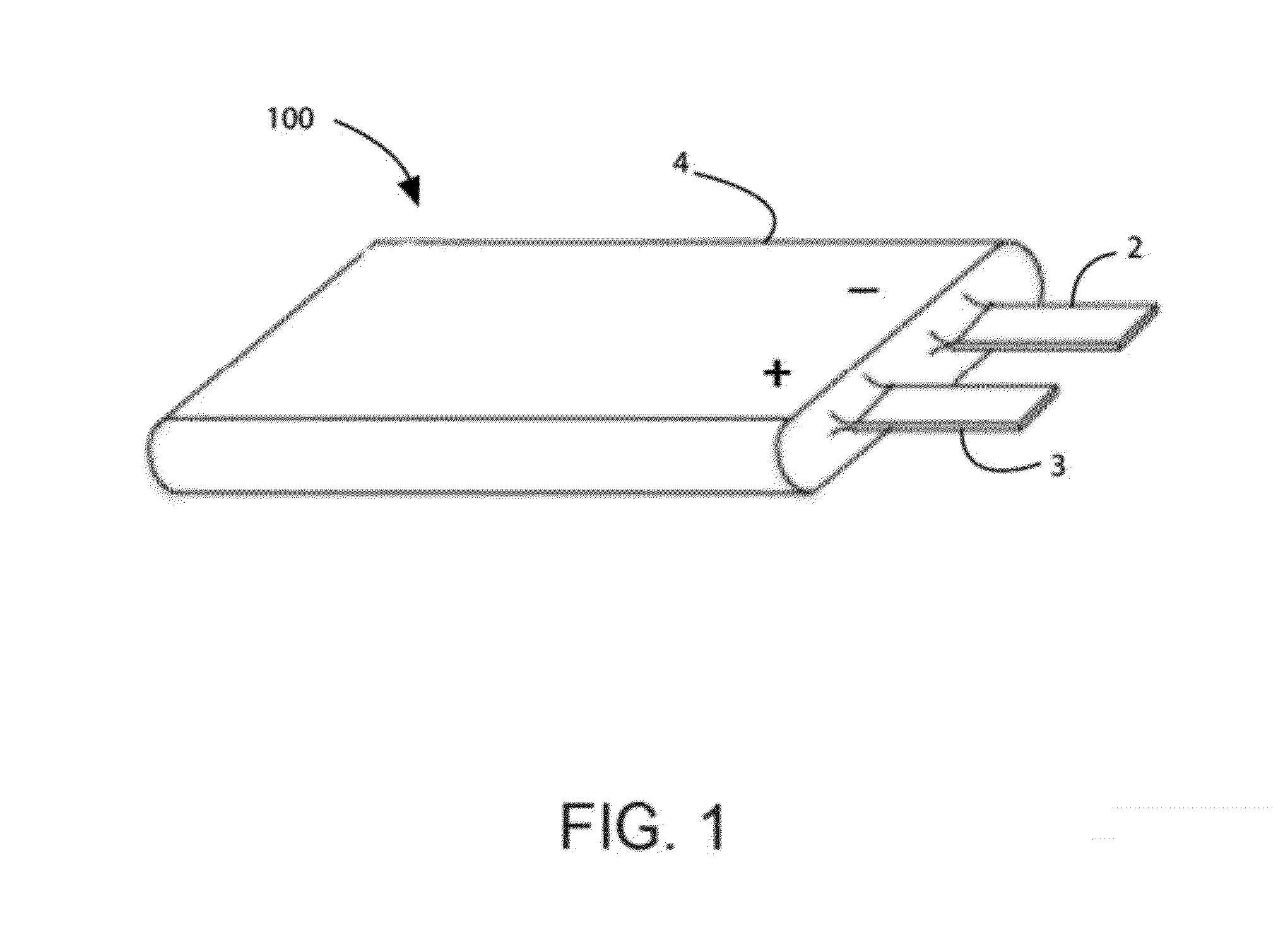
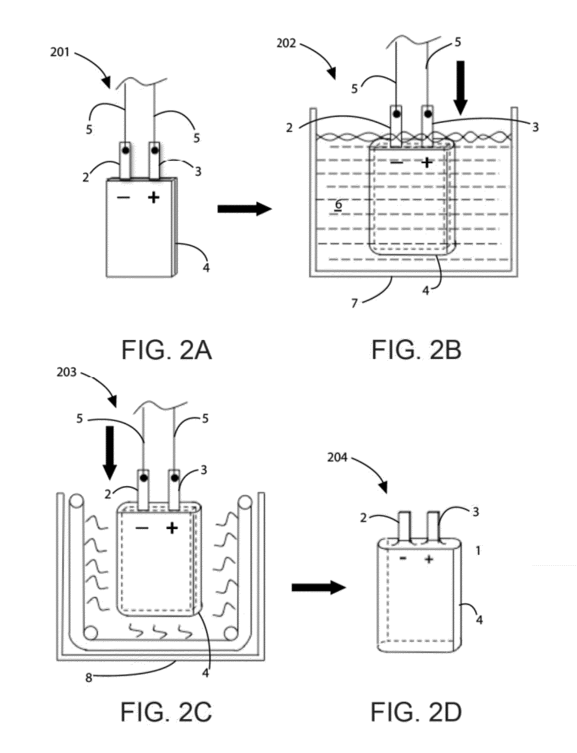
[0013]Benefits are achieved over conventional techniques. Depending upon the specific embodiment, one or more of these benefits may be achieved. In a preferred embodiment, the present invention provides a hermetic packaging device for a solid-state battery and a method for making same. In a specific embodiment, the present invention provides a method for applying polymer based coatings by dip coating spraying, powder coating or otherwise forming thin protective conformal sheath around the cell that has specific functions. Preferably, the protective sheath may be comprised of several functionally graded over layers that are applied to achieve hermetic protection of the device, static discharge protection and mechanical protection. The coatings may also contain materials for gettering or desiccants. Preferably, the present package and method protects the active components from atmospheric elements and at the same time minimizes the parasitic mass and volume to optimize the battery energy density. Preferably, the present invention includes a method and device for a conformal solid-state package, which can accurately encapsulate a battery device, while protecting the battery electrically, mechanically, and environmentally. Of course, there can be other variations, modifications, and alternatives.

Problems solved by technology

The laminated heat seal material itself is relatively thick (50-100 microns) and difficult to form conformally around the active battery materials and so the packaging itself and voids between it and the cell layers form a parasitic mass and volume that detracts from the overall energy density of the cell it is enclosing.

Method used


Image

  • Conformal solid state package method and device for a battery device
  • Conformal solid state package method and device for a battery device
  • Conformal solid state package method and device for a battery device

Examples


Embodiment Construction

[0020]According to the present invention, techniques related to manufacture of electrochemical cells are provided. More particularly, the present invention provides a method and device for packaging a solid-state thin film battery device. Merely by way of example, the invention has been provided with use of lithium based cells, but it would be recognized that other materials such as zinc, silver, copper and nickel could be designed in the same or like fashion. Additionally, such batteries can be used for a variety of applications such as portable electronics (cell phones, personal digital assistants, music players, video cameras, and the like), power tools, power supplies for military use (communications, lighting, imaging and the like), power supplies for aerospace applications (power for satellites), and power supplies for vehicle applications (hybrid electric vehicles, plug-in hybrid electric vehicles, and fully electric vehicles). The design of such batteries is also applicable ...


PUM

PropertyMeasurementUnit
resistivityaaaaaaaaaa
diffusion coefficientaaaaaaaaaa
spatial volumeaaaaaaaaaa

Abstract

A monolithically integrated thin-film solid-state lithium battery device to supply energy to a mobile communication device. The device includes a plurality of layers ranging from greater than 100 layers to less than 20,000 layers of lithium electrochemical cells, which may be connected in parallel or in series to conform to a spatial volume. The device also includes a polymer based coating characterized by a thickness to house the plurality of layers and configured as an exterior region for the battery device, the polymer based coating having a resistivity of 1012 Ω.cm and higher. The device further includes a hermetic seal provided by the polymer-based coating to enclose and house the plurality of layers.

Description

CROSS-REFERENCES TO RELATED APPLICATIONS[0001]The present application incorporates by reference, for all purposes, the following pending patent application: U.S. patent application Ser. No. 13 / 283,528, filed Oct. 27, 2011 (Attorney Docket No. 913RO-001300US), commonly assigned.BACKGROUND OF THE INVENTION[0002]This present invention relates to manufacture of electrochemical cells. More particularly, the present invention provides a method and device for packaging a solid-state thin film battery device. Merely by way of example, the invention has been provided with use of lithium based cells, but it would be recognized that other materials such as zinc, silver, copper and nickel could be designed in the same or like fashion. Additionally, such batteries can be used for a variety of applications such as portable electronics (cell phones, personal digital assistants, music players, video cameras, and the like), power tools, power supplies for military use (communications, lighting, imag...

Claims


Application Information

Patent Timeline
Patent Type & Authority Applications(United States)
IPC IPC(8): H01M10/02H01M4/26B05D3/12B05D1/02C23C4/12B05D1/18H01M10/04B05D5/00H01M50/121H01M50/124H01M50/131H01M50/133H01M50/14
CPCH01M2/0277H01M2002/0297H01M10/04H01M2/0285Y02E60/10H01M50/131Y02P70/50H01M10/058H01M50/133H01M50/121H01M50/14H01M50/124
Inventor BUCKINGHAM, STEPHENLUKICH, SVETLANASASTRY, ANN MARIELANGLOIS, MARC
Owner SAKTI3
Why Eureka
Try Eureka