Back-up fuel cell electric generator comprising a compact manifold body, and methods of managing the operation thereof

Active Publication Date: 2012-05-31
ELECTRO POWER SYST MFG SRL
View PDF4 Cites 7 Cited by
  • Summary
  • Abstract
  • Description
  • Claims
  • Application Information

AI Technical Summary

Benefits of technology

[0024]One or more embodiments of the present invention provide a fuel cell electric generator specifically devised for back-up, which allows the reduction of plant and management costs as well as the increase of efficiency and reliability of the generator, while at the same time reducing the bulkiness thereof. Further, one or more embodiments of the present invention provide a fuel cell electric generator having a more efficient thermal integration between stack cooling circuit and reagent feed circuit is achieved.
[0025]One or more embodiments of the present invention provide methods for managing the operation of such a fuel cell-based back-up electric generator which increase the overall efficiency thereof during both the crucial phases of start-up and shut-down as well as under regular working conditions.

Problems solved by technology

It is necessary that the reacting gases be humidified because it is thanks to the water molecules that the passage of protons across the polymeric membrane occurs: too low a degree of humidification leads to a reduced passage of protons from the anode compartment to the cathode compartment with a consequent worsening of the fuel cell performance, whereas too high a degree of humidification may cause the occlusion of the catalytic sites with a consequent deterioration of the fuel cell performance.
The ensemble of all the elements forming hydraulic connections between the stack passageways and other major elements of the fuel cell electric generator (e.g. the sources of reagents) generally occupy a significant space and contribute largely to the overall weight of the system.
Further, the time needed for their assembling represents a significant part of the time needed to assemble the whole system.
In turn, this 
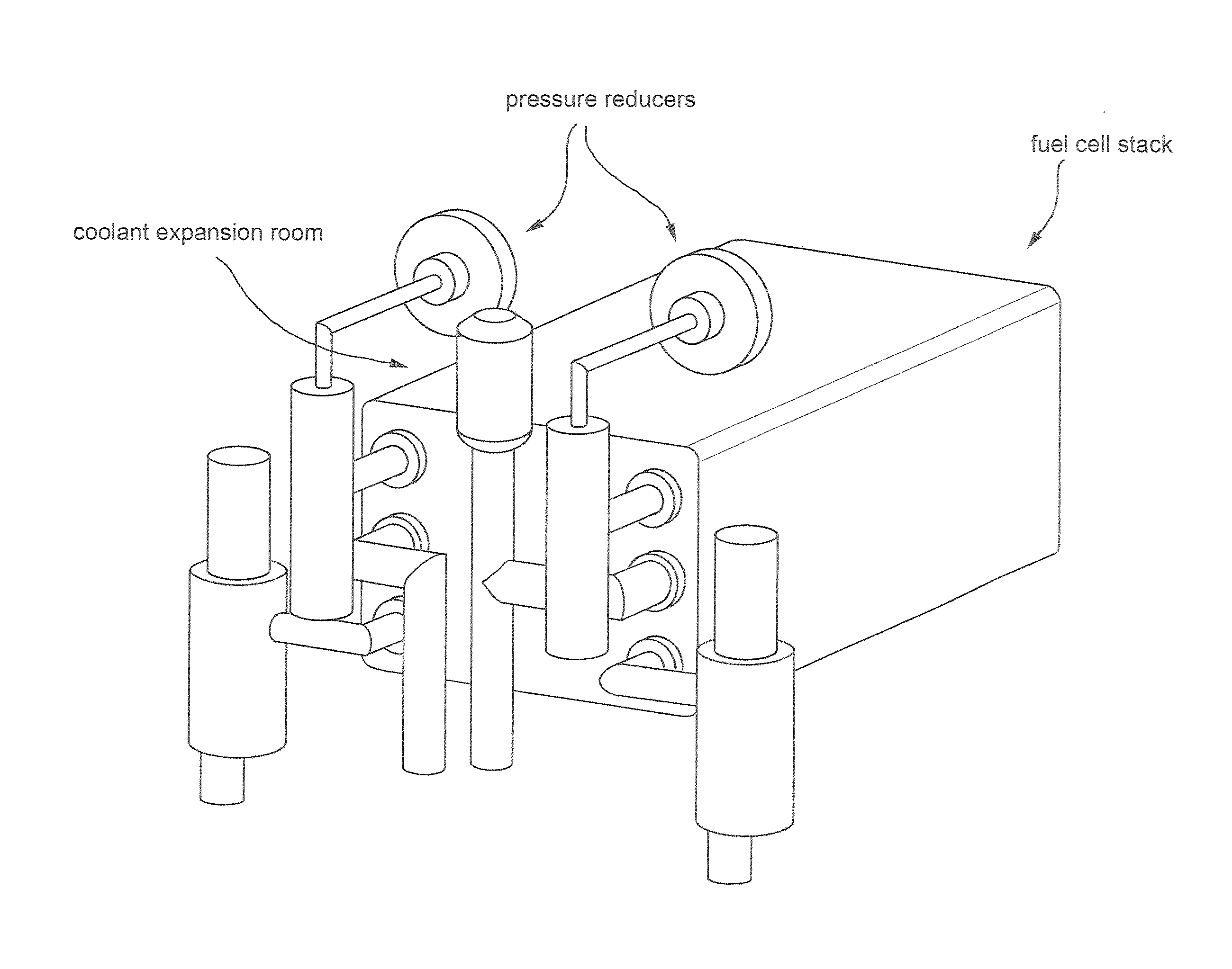
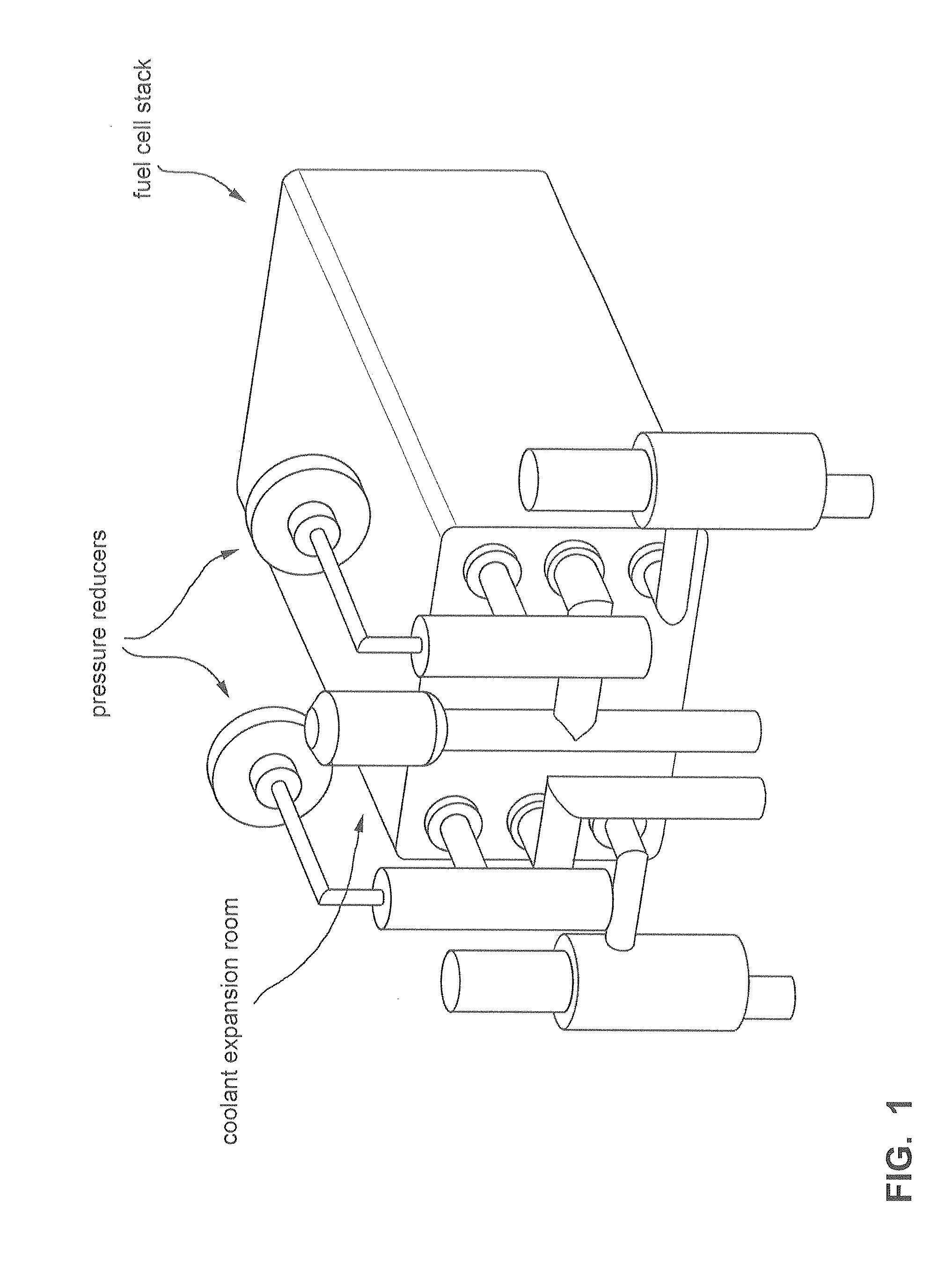
assembly time directly affects the overall cost of the fuel cell electric generator. FIG. 1 illustrates a view of a known fuel cell electric generator wherein the stack is connected to a plurality of conduits through which reagents are fed to the fuel cells and reaction products are split into two currents, one of which is re-circulated to the stack while the other one is ultimately expelled from the system.
However, in this arrangement, humidity regulation and control is complicated by a number of factors.
Firstly, fresh reagents fed to the anode and cathode compartments undergo expansion prior to reaching their respective mixing rooms in the manifold.
As a consequence, their temperature decreases, very often dropping below room temperature.
As a result, when these dry and cold flows are mixed with the humid re-circulated exhaust flows in the manifold body mixing rooms, their low temperature may cause excessive condensation of the water carried by the exhaust flows, thus undesirably reducing the resulting humidity of the flow leaving the manifold body to enter the stack, which may thus be too dry to ensure fuel cell humidification degrees compatible with the correct operation of the stack.
External humidification means are therefore needed, which disadvantageously increase the complexity of the BoP and affect the time needed for the installation and routine maintenance thereof.
Further, the higher the number of variables, the more complex the control system supervising the operation of the electric generator, which is disadvantageous both in terms of increased costs and reduced reliability.
Because the coolant fluid is in direct contact with the stack elements, in fact, an uncontrolled increase in its pressure thereof may damage the fuel cells at a structural level.
Disadvantageously, such a solution renders the system structure more cumbersome and further complicates the already delicate thermal integration balance.
This, in turn, has repercussions, as described above, also on the humidification of the flows fed to the stack.
As can be immediately inferred from what described thus far, the known embodiments of back-up electric generation systems are relatively expensive and require accurate and careful routine maintenance to prevent their becoming unreliable.

Method used


Image

  • Back-up fuel cell electric generator comprising a compact manifold body, and methods of managing the operation thereof
  • Back-up fuel cell electric generator comprising a compact manifold body, and methods of managing the operation thereof
  • Back-up fuel cell electric generator comprising a compact manifold body, and methods of managing the operation thereof

Examples


Embodiment Construction

[0059]With reference to FIG. 3, there is indicated as a whole with 1 a back-up electric generator devised to supply electric energy to a user 8. The generator 1 comprises an electric conversion module 50 comprising, in turn, a plurality of PEM fuel cells piled in a stack 5, a manifold body 27 and a cell voltage monitoring (CVM) device 39 (see detail in FIG. 4). The generator is further provided with a power conditioning unit 22, which manages the supply of electric power to user 8 by alternatively acting upon switches so that user 8 receives power either from the generator 1 or from other emergency power sources (such as batteries, capacitors, etc.). Further details concerning operation modes managed by the power conditioning unit 22 will be described below.

[0060]A flow of hydrogen in stoichometric excess is supplied to generator 1 from supply means 2, such as a cylinder of technically pure hydrogen. The supply of hydrogen is enabled by valve means 3, including valves that may be ma...


PUM


Abstract

A fuel cell electric generator designed for back-up in the absence of network electricity supply. The generator comprises a fuel cell stack, means for supplying the stack with a first and a second reagent flow comprising, in turn, pressure reducing means, and a manifold body to communicate with the stack said first and second reagent flows and at least a flow of coolant fluid via a respective coolant loop. The manifold body comprises inside chambers for the mixing of said reagent flows with corresponding re-circulated product flows and a coolant fluid expansion chamber within which said pressure reducing means of said first and second reagent flows are positioned at least partially drowned by said coolant. Method for the start-up and shut-down of the generator, and a method for detecting the flooding of a fuel cell and a method for detecting the presence of gas leakages in the generator are also disclosed.

Description

CROSS-REFERENCE TO RELATED APPLICATIONS[0001]This application is a U.S. Nationalization of PCT International Application No. PCT / EP2010 / 051749, filed Feb. 11, 2010, entitled “BACK-UP FUEL CELL ELECTRIC GENERATOR COMPRISING A COMPACT MANIFOLD BODY, METHODS OF MANAGING THE OPERATION THEREOF,” which claims priority to European Patent Application No. 09152671.5, filed Feb. 12, 2009, the entireties of both of the foregoing applications are incorporated herein by reference.TECHNICAL FIELD[0002]Embodiments of the present invention relate to a fuel cell electric generator specifically designed for back-up in the absence of network electricity supply, wherein a plurality of fuel cells are piled into a stack to generate electricity by being supplied with a combustible gas and an oxidising gas, on a fuel electrode (anode) and an oxidation electrode (cathode), respectively.[0003]In particular, embodiments of the invention relate to a fuel cell electric generator comprising an electrochemical co...

Claims


Application Information

Patent Timeline
IPC IPC(8): H01M8/24H01M8/04
CPCH01M8/04097H01M8/04141H01M8/04298H01M8/0432H01M8/04432H01M8/04544Y02E60/50H01M8/04664H01M8/04761H01M8/04768H01M8/04925H01M8/04955H01M8/2415H01M8/04552H01M8/04302H01M8/04225H01M8/2484H01M8/04H01M8/10H01M8/24H01M8/04932
Inventor CHERCHI, PIERPAOLOMERCANTE, LUCAMUSSO, ANDREACEFFA, DARIOBORELLO, LUISAGIANOLIO, GIUSEPPE
Owner ELECTRO POWER SYST MFG SRL
Why Eureka
Try Eureka