Multi-mode communication system for a mobile phone

a communication system and mobile phone technology, applied in the field of multi-mode communication systems for mobile phones, can solve the problems of short range of most such tags, devices are required to compromise the design of single antennas and circuit networks, and cannot be directly attached, so as to reduce or eliminate the effect of coupled loading effect, reduce or eliminate the effect of rfid transceiver antenna on the secure element's antenna, and improve the range and performance of near field devices

Inactive Publication Date: 2012-05-31
WIRELESS DYNAMICS
View PDF13 Cites 128 Cited by
  • Summary
  • Abstract
  • Description
  • Claims
  • Application Information

AI Technical Summary

Benefits of technology

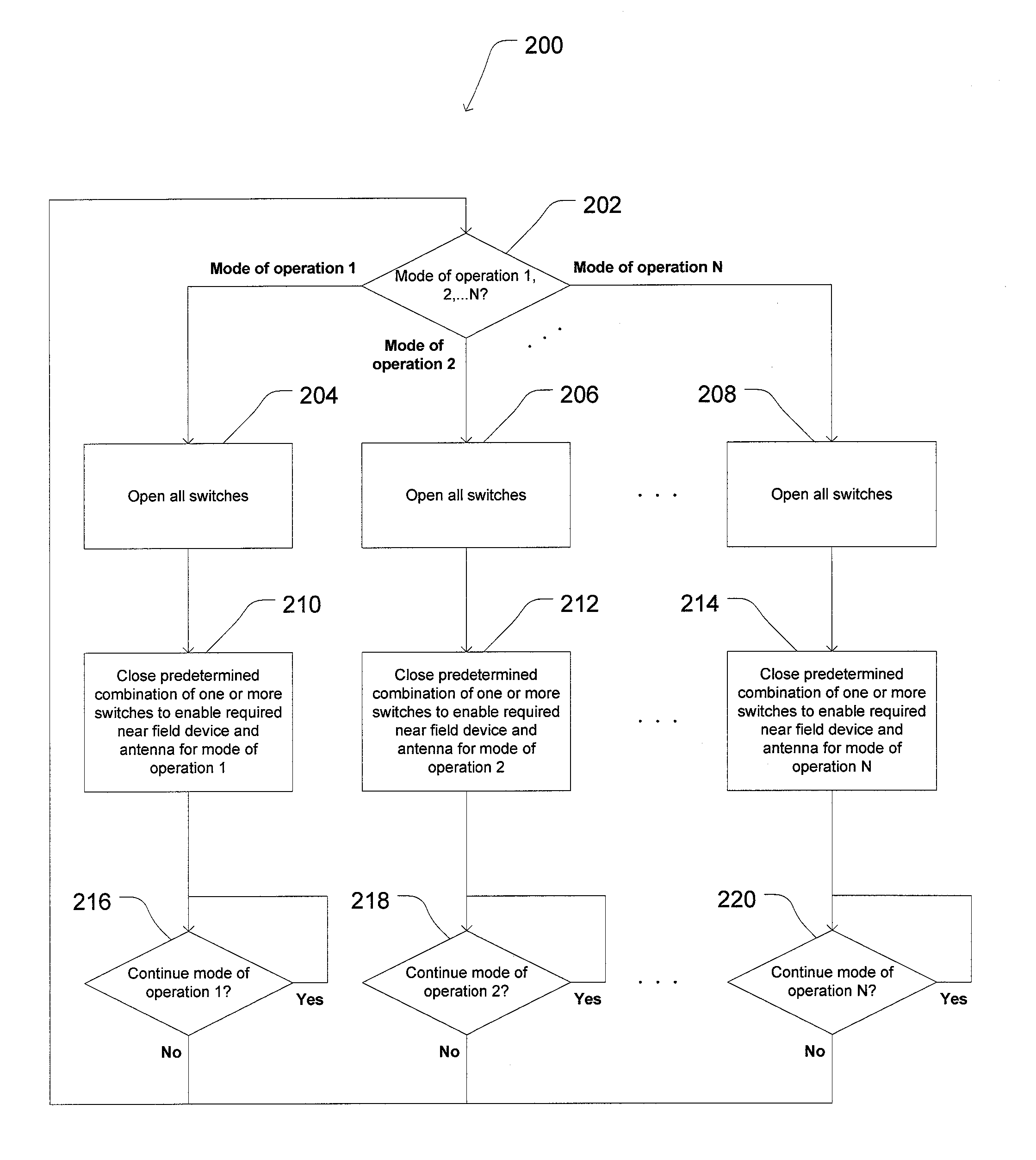
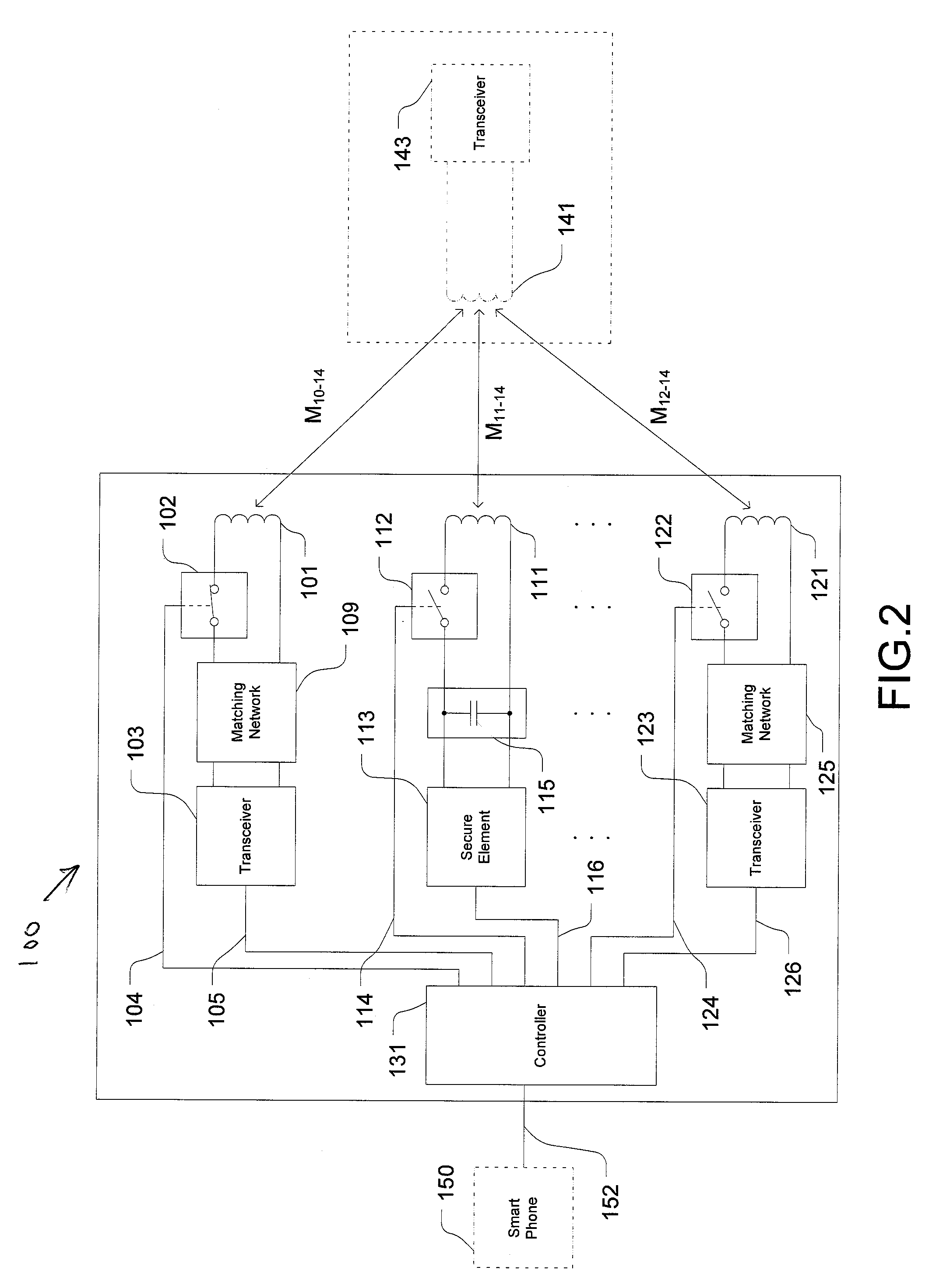
[0021]A preferred embodiment of the present invention comprises a hand-held, near-field, multi-mode communication device for a mobile phone comprising of a plurality of near field devices, including transceivers and / or transponders (secure elements) and associated electromagnetic near-field antennas, for transmitting to, and / or receiving from, an external device. A plurality of switches control the connection of the near field devices to their respective antennas, to isolate the non-operating near field devices and their matching networks. A controller controls the switched state of said plurality of switches, and selects one of a plurality of predeteimined modes of operation available on said hand-held, near-field, multi-mode communication device. By turning off all the antenna switches except those needed for the desired operating mode, the range and performance of the near field devices is improved.
[0022]According to a preferred embodiment of the present invention, multiple antennas are located in close physical proximity to each other within the volume constraints of the device. The switches act as an isolation device to reduce or eliminate the coupled loading effect of the non-operating near field device(s) and their respective matching networks on the active near field device and its respective matching network.
[0023]In one embodiment where the near field devices comprise an RFID transceiver and a secure element, when the switch connecting the secure element to its antenna is open, the secure element antenna loop is broken. As a result, during RFID transceiver operation, the coupled loading of the secure element antenna and its associated resonating capacitor is eliminated. When the RFID antenna switch is open, the effect of the RFID transceiver antenna on the secure element's antenna is mostly eliminated. As a result, during contactless payment transactions, the coupled loading of the RFID transceiver and matching network is eliminated.

Problems solved by technology

However, most such tags are short range, because they function using passive inductive coupling in the near-field, i.e., their range of operation is on the order of a few centimeters to a few tens of centimeters.
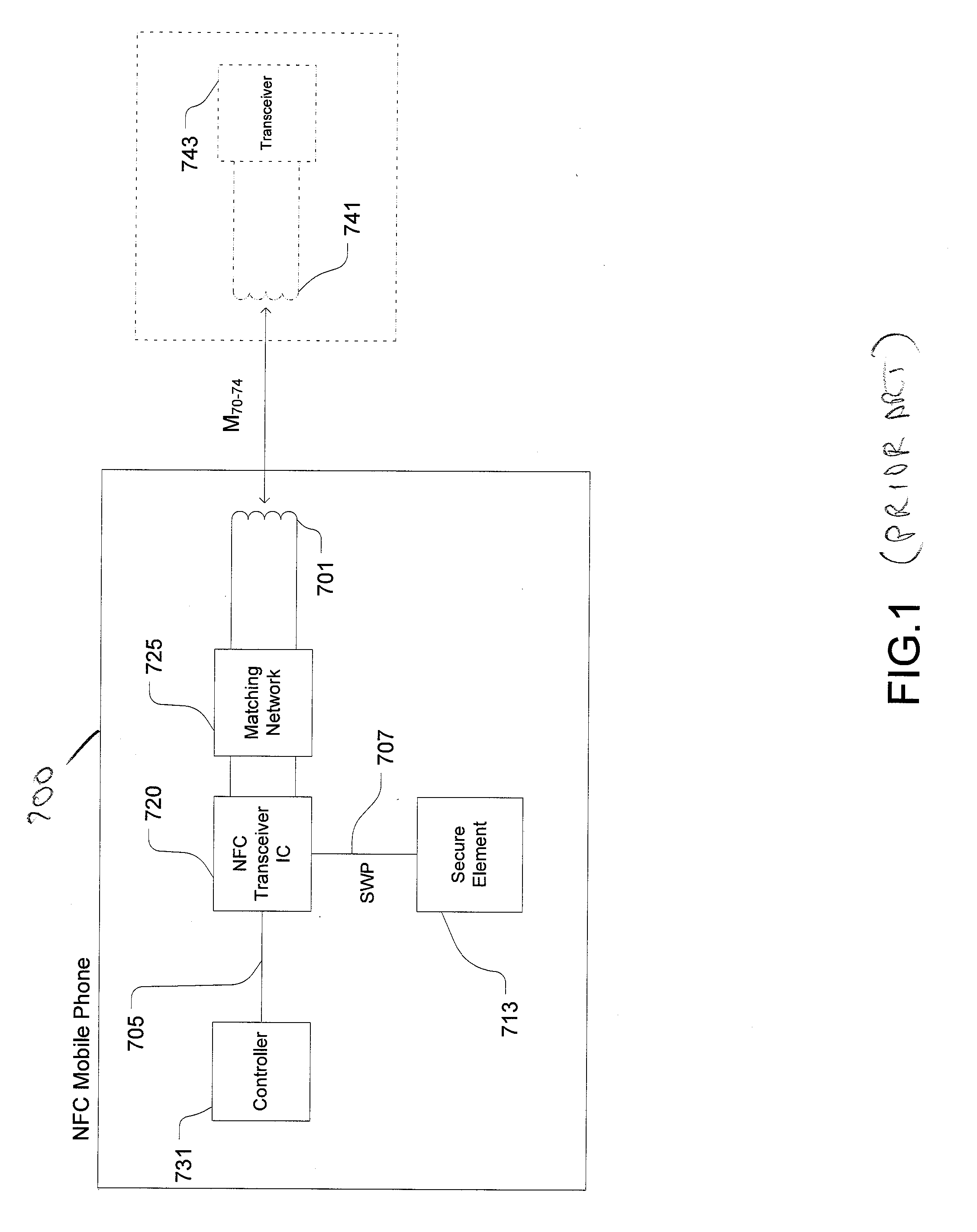
The drawback of this system is that the SE is not directly attached to its own dedicated antenna, for receipt of contactless data, and load modulation of the antenna to send contactless data.
The NFC transceiver 720 matching network 725 is not optimal for passive load modulation on behalf of the SE, so there is a compromise in performance.
A limitation of the prior art is that these embedded systems or external cards being used with mobile phones use a single antenna for both the RFID / NFC transceiver and the secure element.
These prior art devices are therefore required to compromise the design of their single antenna and circuit networks for the divergent requirements of different near field devices.
More specifically, the design and tuning of a single antenna and the design and topology of a single matching network cannot be simultaneously optimized for the divergent requirements of different modes of operation, e.g., where one near field device is generating an active field using the antenna, and where a second near field device operates to vary the termination impedance applied to the antenna to create passive load modulation of the reader's generated field.
The result is compromised range and performance for both modes of operation.

Method used


Image

  • Multi-mode communication system for a mobile phone
  • Multi-mode communication system for a mobile phone
  • Multi-mode communication system for a mobile phone

Examples


second embodiment

[0047]FIG. 4 is a functional block diagram and schematic of a multi-mode communication system for a mobile phone according to the invention. As seen in FIG. 4, the multi-mode communication system 800 includes first and second antennas 801 and 811. A matching network 809 is connected to first antenna 801. A resonant capacitor 815 is connected to the second antenna 811. A first near field device 803 is connected to matching network 809. In one embodiment, first near field device 803 is a conventional NFC / RFID transceiver IC. A second near field device 813 is connected to a second matching network comprising a resonant capacitor 815. In one embodiment, second near field device 813 is a conventional secure element. A first switch 802 is connected between matching network 809 and first antenna 801 and a second switch 812 is connected between resonant capacitor 815 and second antenna 811. A controller 831 controls the switched state of said first and second switches 802, 812 via respectiv...

third embodiment

[0053]FIG. 9 is a functional block diagram and schematic of a multi-mode communication system 900 for a mobile phone according to the invention. In FIG. 9, components corresponding to the components shown in FIG. 4 have the same numbers. As seen in FIG. 9, system 900 is embedded in mobile phone 950 rather than external to the mobile phone, as seen in FIG. 4. Mobile phone 950 includes smart phone electronics 935 to which system 900 is coupled.

[0054]As also seen in FIG. 9, in this embodiment a voltage generator 965 is included in system 900. Voltage generation 965 is connected to antenna 801 via line 960 and functions to generate a voltage from antenna 801 by magnetic induction from a magnetic field when mobile phone 950 is positioned in an area where such a field is being generated by an external device. Voltage generator 965 provides sufficient power to enable the connection of said secure element and resonant capacitor to said second antenna, thus enabling secure element transactio...


PUM


Abstract

A multi-mode communication system for a mobile phone includes a plurality of antennas, a plurality of matching networks, each matching network connected to a respective one of said plurality of antennas, a plurality of near field devices, each near field device connected to a respective one of said plurality of matching networks, each pair of near field device and its associated matching network operative to either load modulate its antenna or generate an active magnetic field via its antenna, a plurality of switches, with one of said switches positioned between each of said matching networks and its respective antenna, and a controller for controlling the switched state of said plurality of switches such that one or more of said near field devices and their respective matching networks are selectively coupled to their respective antennas.

Description

CROSS REFERENCE TO RELATED APPLICATION[0001]This application claims the benefit of U.S. Provisional Application No. 61 / 417,399 filed Nov. 26, 2010, the entirety of which is hereby incorporated by reference.BACKGROUND[0002]Mobile communication devices, including cellular phones, personal digital assistants (PDAs), smart phones, other types of mobile phones, and the like, (herein also collectively referred to as mobile phones or smart phones) are being used not just for communication (voice and text), but also to take photos, send text messages, listen to music, surf the internet, do word processing, watch movies, and the like. Consumers are also becoming interested in using their mobile communication devices to perform various transactions (e.g., transfer funds, purchase products, etc.) traditionally provided by RFID tags, contact credit cards, and contactless credit cards.[0003]Radio-frequency identification (RFID) is a technology that uses radio waves to transfer data from an elect...

Claims


Application Information

Patent Timeline
Patent Type & Authority Applications(United States)
IPC IPC(8): H04B5/00H04W88/06
CPCH04B5/0025H04W88/06H04B5/0062H04B5/00
Inventor ADAMS, DAMONTAM, AMBROSEAGUIRRE-CHARO, CARLOS
Owner WIRELESS DYNAMICS
Why Eureka
Try Eureka