Method for co-processing components in a metal injection molding process, and components made via the same

a metal injection molding and coprocessing technology, applied in the direction of femoral heads, manufacturing tools, prostheses, etc., can solve the problem of not always being able to manufacture complex shaped parts having certain geometries

a metal injection molding and coprocessing technology, applied in the direction of femoral heads, manufacturing tools, prostheses, etc., can solve the problem of not always being able to manufacture complex shaped parts having certain geometries

US20120136400A1Active Publication Date: 2012-05-31HOWMEDICA OSTEONICS CORP

Image

  • Method for co-processing components in a metal injection molding process, and components made via the same
  • Method for co-processing components in a metal injection molding process, and components made via the same
  • Method for co-processing components in a metal injection molding process, and components made via the same

Examples


Embodiment Construction

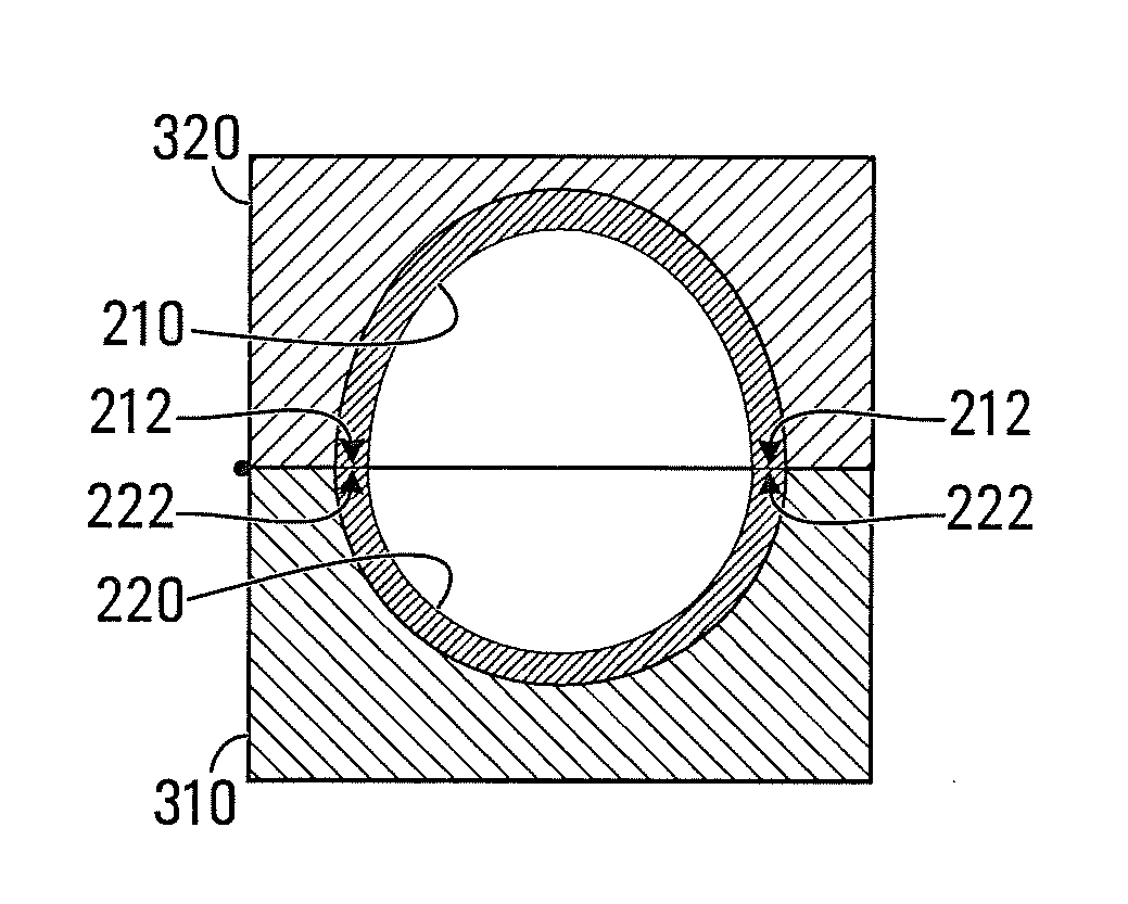
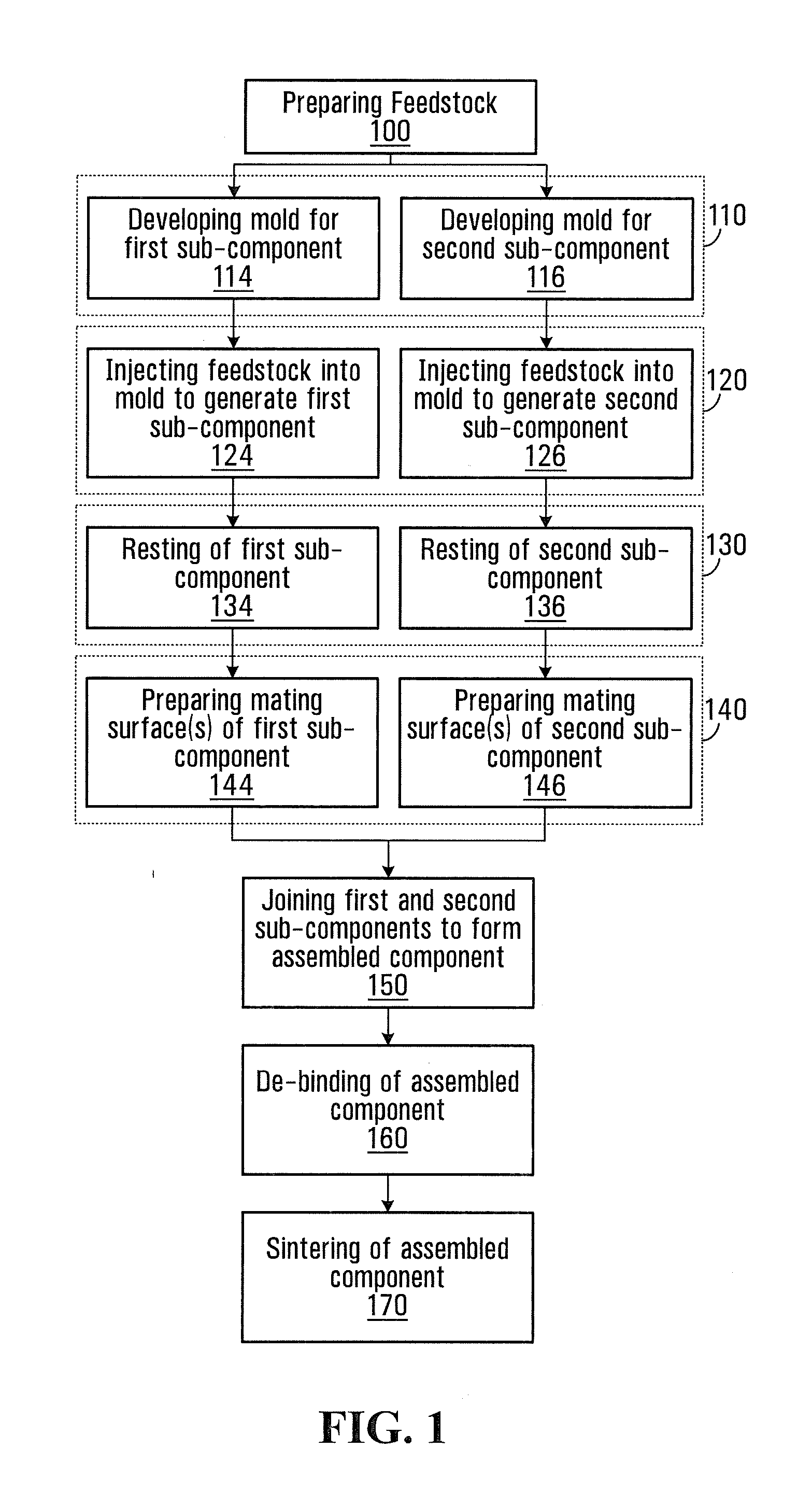
[0027]In accordance with the present invention, three (3) methods are provided for manufacturing a component using metal injection molding (MIM), wherein an assembled component is formed by joining two sub-components together using co-processing techniques. Although these methods share certain processes and procedures, each method will be described separately.

Method 1

[0028]FIG. 1 shows a flow diagram of a first non-limiting co-processing method in accordance with a specific example of implementation of the present invention. As shown, the steps of the co-processing method involve preparing a feedstock for each of the sub-components that are to be joined together, injecting the feedstock(s) into respective molds for producing “green” parts for each of the sub-components, joining the sub-components together to form an assembled component, performing co-debinding for removing the binder from the assembled component while the components are in communication with each other and then sint...


PUM

PropertyMeasurementUnit
Fractionaaaaaaaaaa
Fractionaaaaaaaaaa
Temperatureaaaaaaaaaa

Abstract

A method comprising molding a first component from a first feedstock comprising a first material powder and a first binder, molding a second component from a second feedstock comprising a second material powder and a second binder, placing the first component and the second component in physical communication with each other in order to form an assembled component, removing the first binder and the second binder from the assembled component and performing a sintering operation on the assembled component so as to bond the first component and the second component together.

Description

CROSS REFERENCE TO RELATED APPLICATIONS[0001]This application claims the benefit under 35 USC §119(e) of U.S. provisional patent application Ser. No. 61 / 173,708 filed Apr. 29, 2009. The contents of the above-mentioned patent application are incorporated herein by reference.FIELD OF THE INVENTION[0002]The present invention relates to a method for creating complex shaped parts using a metal injection molding process, and specifically to a method that uses co-processing of two or more sub-components in order to form an integral assembled component.BACKGROUND OF THE INVENTION[0003]Metal injection molding (or MIM) is a relatively cost-effective manufacturing process used to produce parts or components with complex shapes from materials such as metals, metal alloys, ceramics, cemented carbides and cermets (ceramic-metal composites), among others. MIM may be used to produce metallic and / or ceramic components with more complex shapes than could be produced using traditional manufacturing te...

Claims


Application Information

Patent Timeline
31 May 2012
Publication
US20120136400A1
IPC
A61B17/56; B28B5/00; B22F7/06
CPC
A61F2/28; C22C1/08; A61F2/3609; A61F2002/30004; A61F2002/30011; A61F2002/30968; A61F2002/30975; A61F2002/3619
Inventors
JULIEN, BENOIT; BOISCLAIR, MATHIEU