Control System and Method for Managing Wireless and Wired Components

a control system and wireless and wired technology, applied in adaptive control, program control, instruments, etc., can solve the problems of increased transmission error probability, inability to match data contained in a broadcast response to the wireless device actually providing the data, and inability to implement control strategies using traditional wired control techniques. energy-saving

Active Publication Date: 2012-05-31
HUBBELL LIGHTING INC
View PDF3 Cites 195 Cited by
  • Summary
  • Abstract
  • Description
  • Claims
  • Application Information

AI Technical Summary

Benefits of technology

[0018]In another exemplary implementation of an embodiment of the present invention, a system provides plug and play support for occupancy sensors, daylight sensors and switch stations. An exemplary system will automatically and intelligently respond to connected devices to provide the most energy efficient operation.

Problems solved by technology

The use of RF wireless control strategies will enable deployment of control strategies not possible or economically prohibitive using traditional wired control techniques.
That is, without the “From” information, data contained in a broadcast response cannot be matched to the wireless device actually providing the data.
Drawbacks of such conventional communication protocols and message formats include: (1) a longer message structure, which may result in greater likelihood of transmission errors in a wireless communication; (2) a more complicated communication protocol, which may require mapping of communication paths between local gateways and wireless devices to ensure efficient delivery of commands and responses; (3) need for additional processing capability in wireless devices to ensure proper transmission and re-transmission of responses, which may increase the cost of deploying and maintaining the system; and (4) limited capability to associate sensors with actuators, which inhibits flexibility to deploy and commission wireless devices, sensors or actuators to monitor and control lighting in selectively defined locations within a three-dimensional space or volume.

Method used


Image

  • Control System and Method for Managing Wireless and Wired Components
  • Control System and Method for Managing Wireless and Wired Components
  • Control System and Method for Managing Wireless and Wired Components

Examples


Embodiment Construction

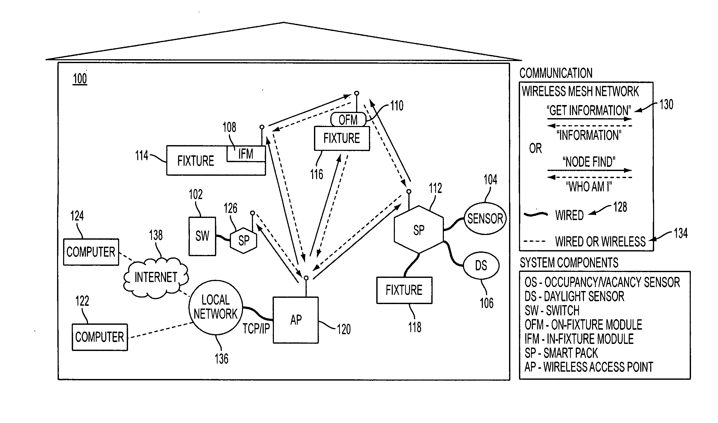
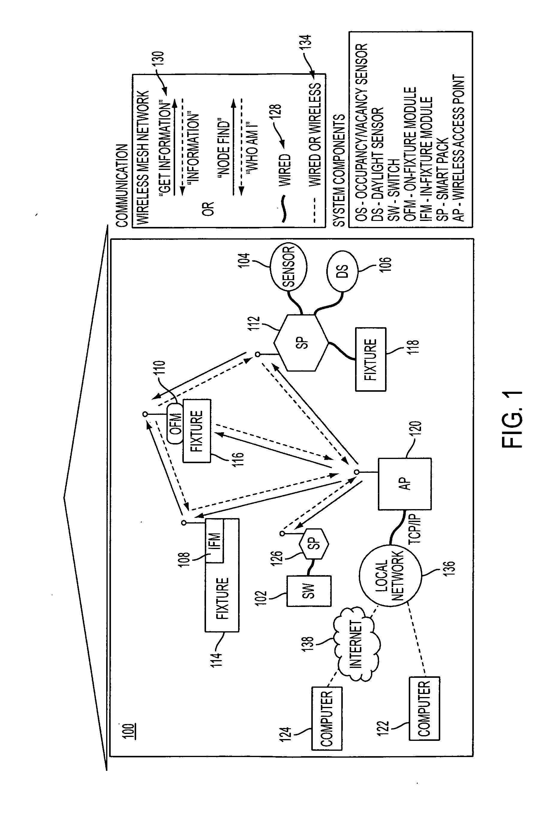
[0041]Referring now to the drawings, wherein like reference numerals designate identical or corresponding parts throughout the several views, embodiments of the present invention are shown in schematic detail.

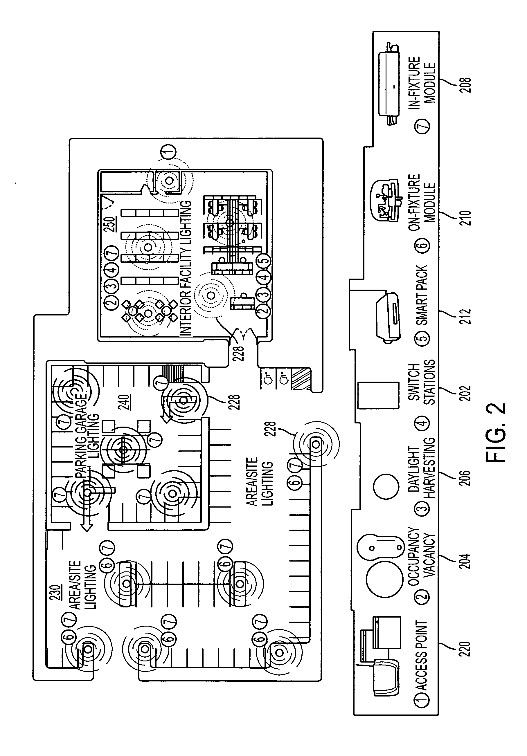
[0042]The matters defined in the description such as a detailed construction and elements are nothing but the ones provided to assist in a comprehensive understanding of the invention. Accordingly, those of ordinary skill in the art will recognize that various changes and modifications of the embodiments described herein can be made without departing from the scope and spirit of the invention. Also, well-known functions or constructions are omitted for clarity and conciseness. Exemplary embodiments of the present invention are described below in the context of commercial application (e.g., office buildings, outdoor parking lots and parking garages). Such exemplary implementations are not intended to limit the scope of the present invention, which is defined in the appended clai...


PUM


Abstract

System and method provide wireless distributed lighting control systems implementing a secure peer-to-peer, self-organizing and self-healing mesh network of actuators and system inputs. The system and method can be designed specifically for indoor and outdoor lighting where actuators include in-fixture, on-fixture and circuit control modules with ON/OFF and full range dimming capabilities, and system inputs include occupancy/vacancy sensors, daylight sensors and switches. A unique messaging protocol facilitates wireless and wired communication between actuators and system inputs, and provides web-based commissioning and monitoring of the lighting control system using a wireless access point accessible from a local network or Internet which can provide an intuitive and easy to use Graphical User Interface (GUI).

Description

CROSS-REFERENCE TO RELATED APPLICATION[0001]This application claims benefit under 35 U.S.C. §119(e) of U.S. provisional patent applications Ser. No. 61 / 415,721 filed Nov. 19, 2010, and Ser. No. 61 / 527,058 filed Aug. 24, 2011, the disclosures of both of which (including all attachments filed therewith on Nov. 19, 2010 and Aug. 24, 2011, respectively) are hereby incorporated by reference in their entirety.BACKGROUND OF THE INVENTION[0002]1. Field of the Invention[0003]The invention is in the field of wireless and wired lighting control systems. Generally, the system provides a solution for wirelessly controlling indoor and / or outdoor lighting luminaires or fixtures. The system includes wireless devices that receive signals from various sensors and other control devices and respond by taking appropriate action to control, for example, the light output of light fixtures. These wireless devices communicate with each other via a radio module (RM) embedded in each device. A controlling use...

Claims


Application Information

Patent Timeline
Patent Type & Authority Applications(United States)
IPC IPC(8): G05B13/00
CPCG05B15/02H05B37/0272G05B2219/2642H05B47/19Y02B20/40
Inventor WEBER, THEODORE E.ARBOUW, TERRENCE R.BENDER, RONALD K.CUMMINGS-KRALIK, RONALD J.CRANE, MICHAEL D.HARTNAGEL, THOMAS J.MARTIN, ROBERT A.MOYLE, PETER A.SMITH, GREGORY F.ZITZ, STEPHAN K.
Owner HUBBELL LIGHTING INC
Why Eureka
Try Eureka