
Hand tool stand

a technology for tools and stands, applied in the field of stands, can solve the problems of tripod effect and may become somewhat unstabl

Inactive Publication Date: 2012-06-07
KIMBALL KIM S
View PDF15 Cites 23 Cited by
  • Summary
  • Abstract
  • Description
  • Claims
  • Application Information

AI Technical Summary

Benefits of technology

[0013]In one aspect, a tool consists of an attachable means that is secure to the handle of a hand tool in which a retractable arm or arms as the case may be are secured. The retractable arm, when unfolded and extended maintains the tool in an upright position while the tool is at rest. The arm or arms may rotate up or down manually as needed from its attachment to the handle. When unfolded downward the arm maintains the handle of the tool in an upright position and off the ground. This makes the tool visibly accessible to the operator, and visible to those in the work area. The tool stand device of the present invention can quickly be retracted manually and secured into the closed position against the handle when the operator desires to resume work.
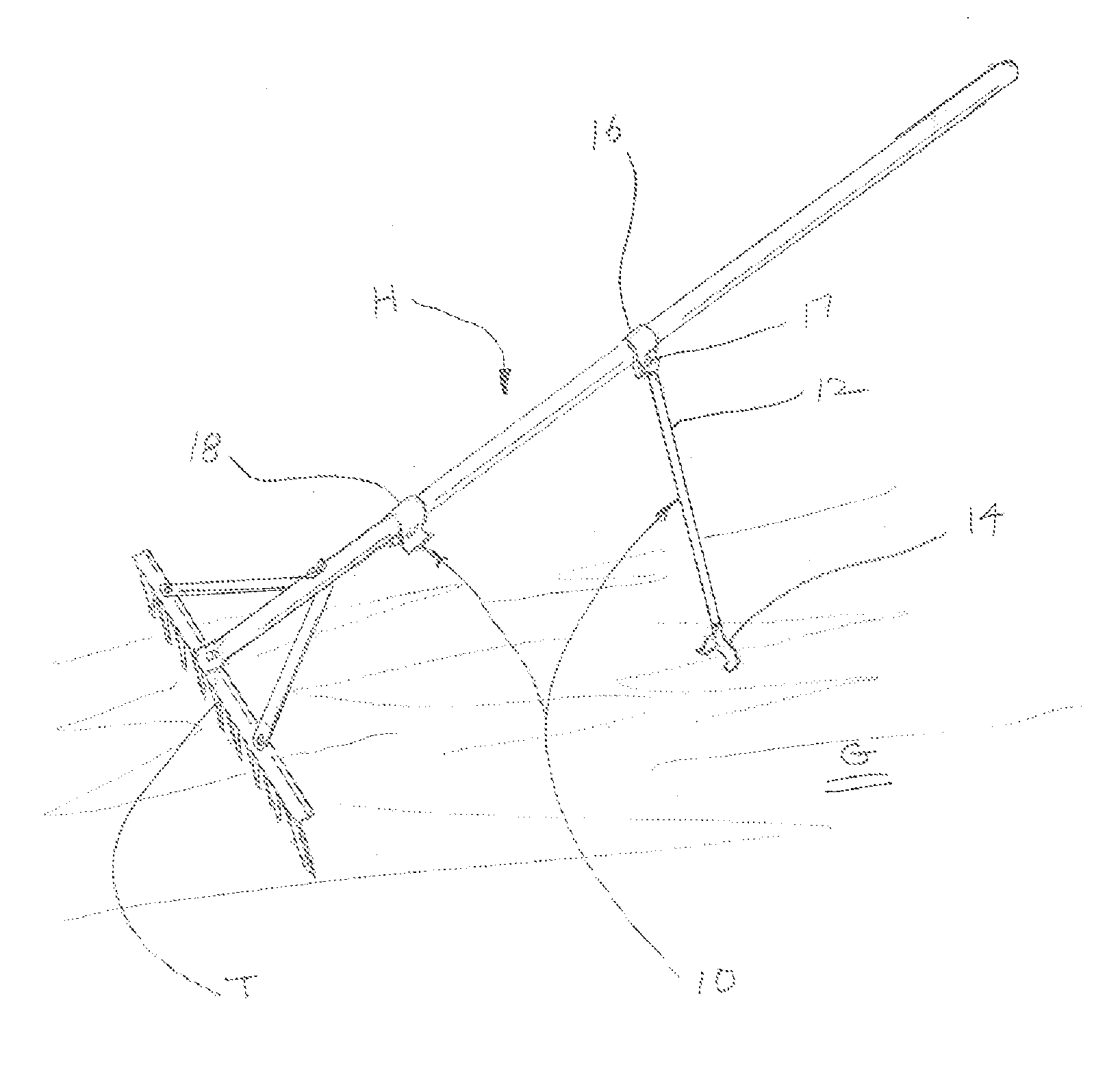
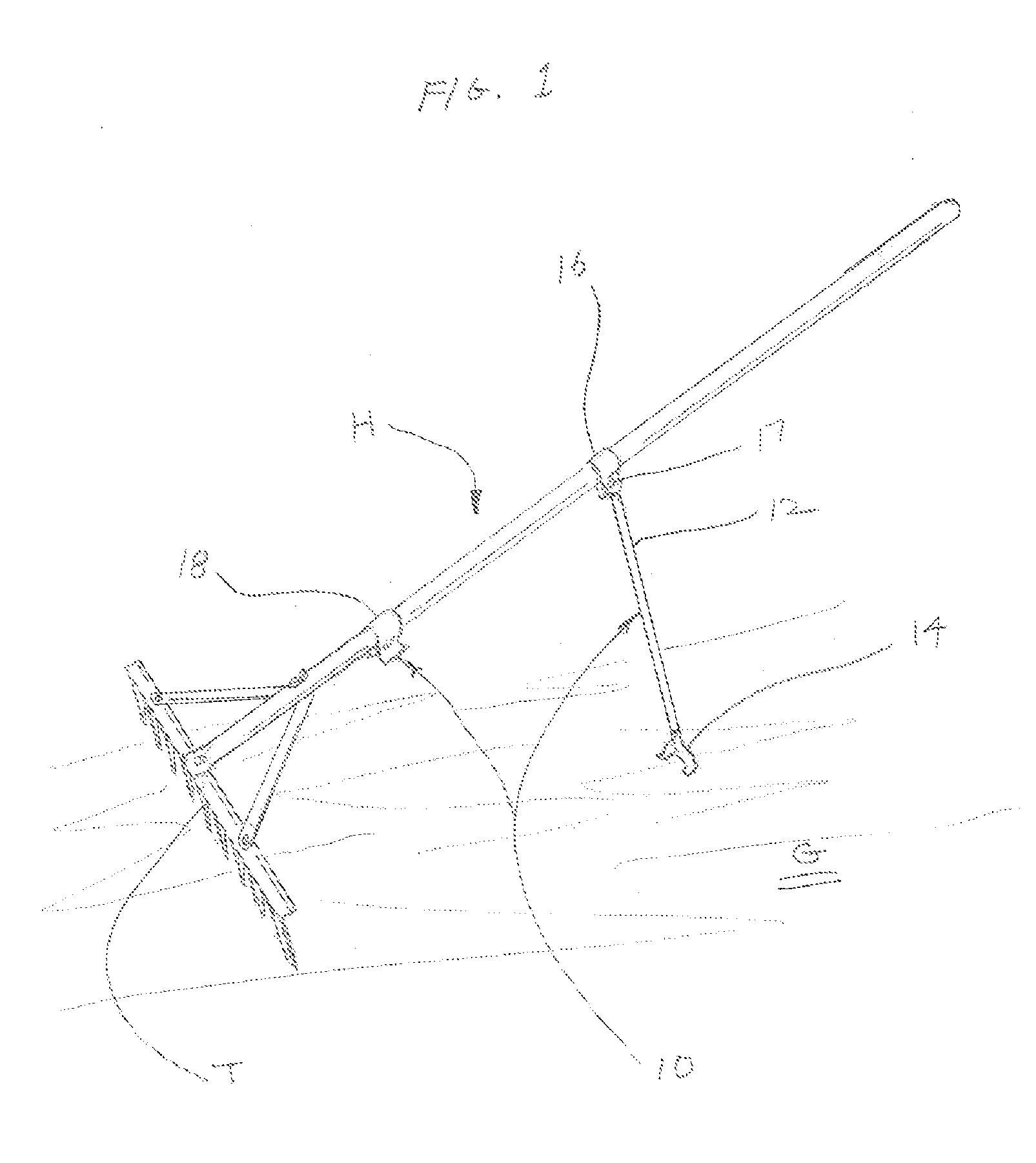
[0015]Implementations of the above aspect can include the following. The tool can be made with the device “built into” the handle, making the device and the handle one complete unit that is flush with the handle. In other words the retractable arm is attached directly to the handle itself. It may also form-fit the handle without being obtrusive. When the present invention is installed, and the arm or arms of the stand are deployed from the handle downward resting atop the ground surface, the tool head and tool handle combined with the stand creates two or more contact points that provide stability to the tool in an upright position. The reason that only two points of contact may provide stability is that at least one of the two is broad enough across its base to form at least a three-point disposition, similar to that of a tripod. For example the tool head on a rake spreads two to three feet across, and with a second point being the retractable arm, there is a tripodal effect. This tripodal effect consists of the two outer ends of the rake and the single retractable arm of the present invention.
[0017]Advantages of the preferred embodiments may include one or more of the following:1) Provide a stabilizer for maintain a hand tool in an upright disposition;2) Create a safer work environment by reducing tripping over tools;3) Eliminate the need for leaning unstable tools against or onto objects;4) Eliminate the problem of tools sliding off, slipping or falling when placed against an object;5) Make hand tools convenient to use;6) Reduce loss of hand tools by making hand tools more viable;7) Reduce breakage or damage of hand tools by keeping them off the ground;8) Make a standalone unit easy to install on existing tool handles;9) Make the hand tool stand device an inexpensive attachment;10) Make the handles with the hand tool stand device part of a complete unit that is retractable into the handle.11) Provide a hand tool stand-up device with one or more stabilizing arms or in some cases a wider base unit on the stand itself.
[0018]Other advantages of the preferred embodiments may include one or more of the following. The stand for handled tools of the present invention overcomes the problems associated with prior art. The present invention is a device that is designed specifically for the use with hand tools to enhance the stability, workability, safety and functionality of garden, maintenance, landscape, construction and household tools. The present invention is adaptable to most hand tools that are able to create a tripodal effect. In other words it has the same type of stabilizing properties as that of a tripod.
[0019]By employing the tool, the need to bend down and pick up the hand tool is eliminated, thus creating better accessibility to the tool later on when needed. In addition there is no need to lean the tool against other objects which eliminates the risk of the tool falling or causing damage if it slides away. The hand tool stand device is a complete unit and attachable to any hand tool handle and may be installed easily to existing hand tools. It may also be standard equipment with replacement handles, with the hand tool stand device already attached.

Problems solved by technology

As can be easily understood, this combination presents a tripodal effect due to the broad width of tool head T. The positioning of hand tool stand 10 is important and cannot be too near the top end of handle 20 as would then tend to lose the tripodal effect and may become somewhat unstable.

Method used


Image

  • Hand tool stand
  • Hand tool stand
  • Hand tool stand

Examples


Embodiment Construction

A. Description of the Present Invention

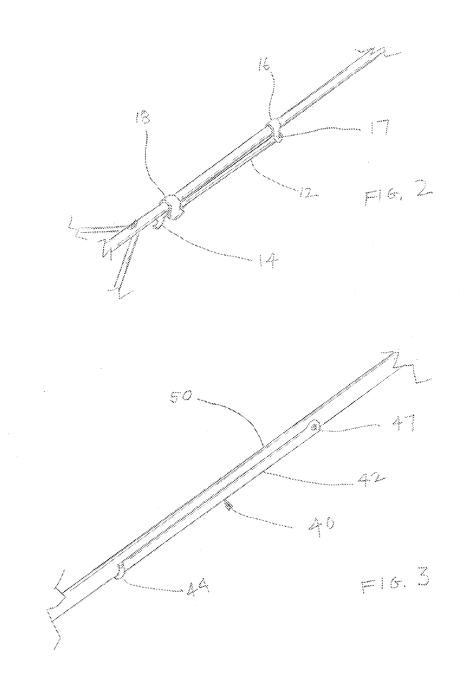
[0026]In FIG. 1 the present invention 10 consists of hand tool H (in this instance a rake), with a handle 20 and a tool head 30. The present invention, hand tool stand 10 consists of a standup shaft 12, a foot 14, a keyhole shaped adapter 16, pivot pin 17, and a socket holder 18. Keyhole adapter 16 has a U-shape similar to that of shower ring or a common plumbing pipe hanger. As shown, keyhole adapter 16 wraps around handle 29 and secures the upper end of shaft 12 onto adapter 16 by having pivot pin 17 threaded through shaft 12.

[0027]As illustrated, hand tool stand 10 is in an upright disposition off of ground G, with standup shaft 12 extended downward with foot 14 resting firmly on ground G, thus supporting hand tool H. As illustrated, handle 20 extends outward and upward into the air, above ground surface G. In this upright disposition, hand tool H is clearly off the ground and visible to other persons or workers in the area, thus eliminating...


PUM


Abstract

A hand tool (or an add-on accessory for the hand tool) with a handle includes one or more retractable arms that, when unfolded and extended maintains the tool in an upright position while the tool is at rest; and an attachment coupling the one or more retractable arms to the handle, the one or more arms rotatably engaged to attachment and the handle and when unfolded the one or more arm maintains the handle in an upright position off the ground to make the tool visible to an operator, wherein the one or more arms are retracted and secured into a closed position against the handle when the operator desires to resume work.

Description

[0001]This application claims priority to Provisional Application 61 / 458,950 filed Dec. 6, 2010 and 13 / 281,423 filed Oct. 25, 2011, the contents of which are incorporated by reference.BACKGROUND OF THE INVENTION[0002]The present invention relates generally to a stand to be used on the handles of hand tools; more specifically it relates to a retractable stand device that can be attached to the handles of garden, construction, landscaping, maintenance, and household hand tools that holds the handle in an upright position for safety and ease of use in a working environment.DESCRIPTION OF RELATED ART[0003]Various types of stands are used to hold or prop up various types of items for greater convenience of use. They come in many shapes and sizes with specific uses and purposes as needed to assist in the use of a specific item. For example, stands are commonly used to prop up items like signs, bicycles, telescopes, artwork, cameras, equipment, displays etc. Most stands are used to keep it...

Claims


Application Information

Patent Timeline
IPC IPC(8): B25G1/00A01B39/08A01D7/00E01H5/02A01B1/00A01B1/20
CPCA01B1/02A01D7/00Y10T16/44E01H5/02B25G1/04
Inventor KIMBALL, KIM S.
Owner KIMBALL KIM S
Learn More