In-line strainer with tension control mechanisms for use on high tensile wire

Inactive Publication Date: 2012-06-07
WOODSTREAM CORP
View PDF10 Cites 49 Cited by
  • Summary
  • Abstract
  • Description
  • Claims
  • Application Information

AI Technical Summary

Benefits of technology

[0017]Another object of the present invention is to provide an in-line strainer in accordance with the preceding objects that is not complex in structure and which can be manufactured at low cost but yet effect

Problems solved by technology

However, “reading” the spring is often a matter of interpretation, leaving the installer uncertain as to whether the correct pre-tension level has been reached.
The manner in which the failure occurs after maximum load has been exceeded is unpredictable and random, which can result in injury to the person installing the fence or other collateral damage, as significan

Method used


Image

  • In-line strainer with tension control mechanisms for use on high tensile wire
  • In-line strainer with tension control mechanisms for use on high tensile wire
  • In-line strainer with tension control mechanisms for use on high tensile wire

Examples


first embodiment

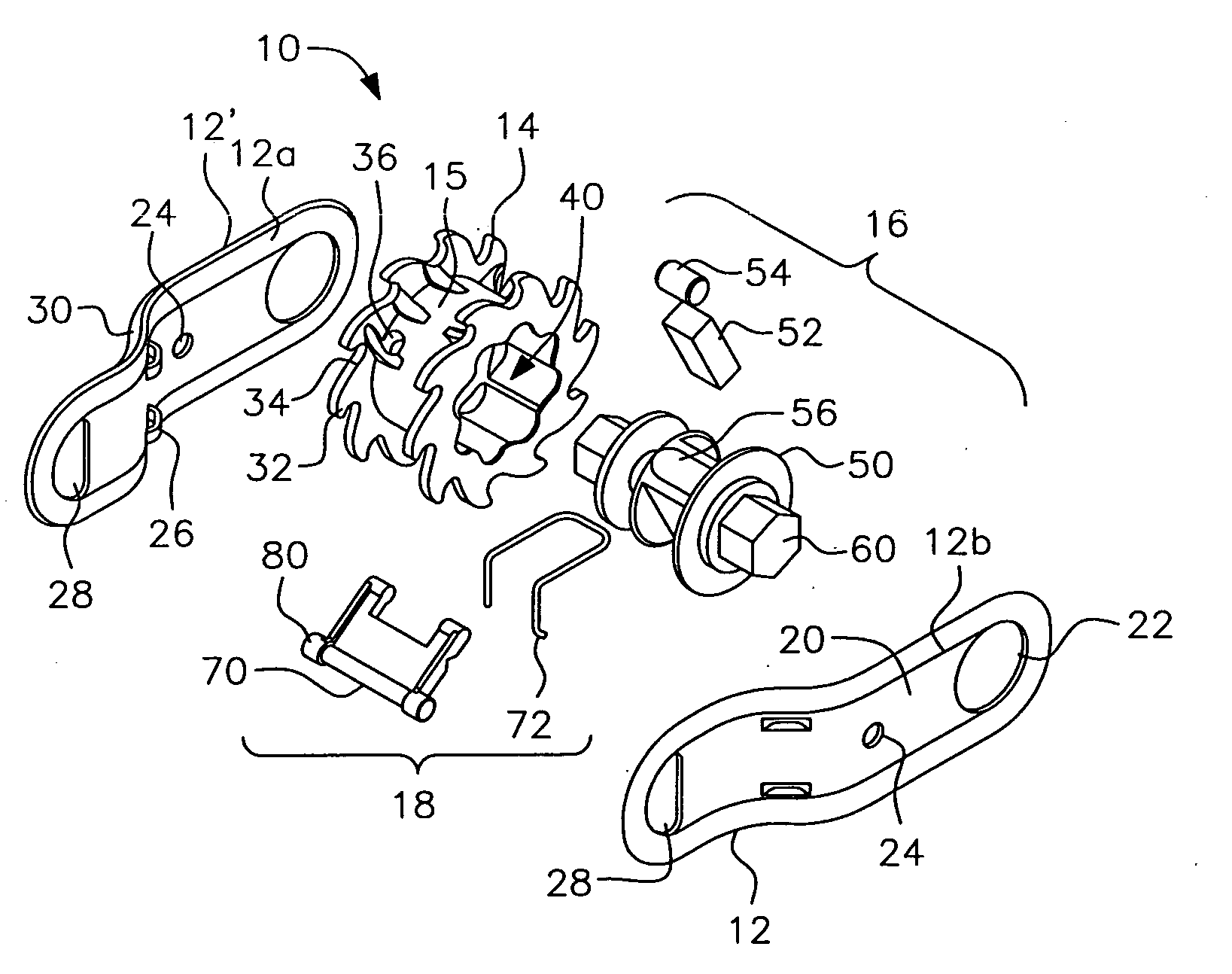
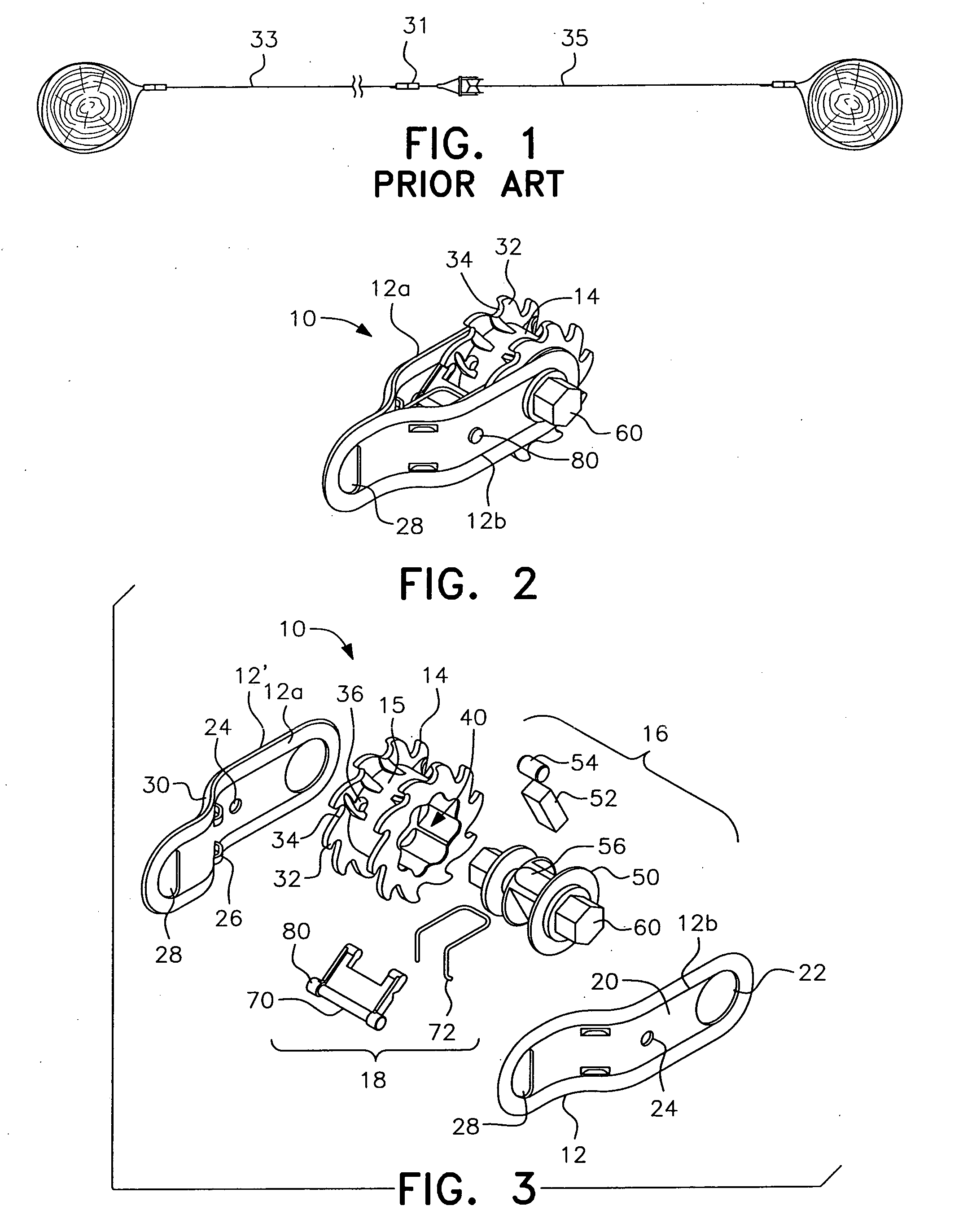
[0090]As shown by a first embodiment in FIGS. 2 and 3, and in more detail on a component by component basis in FIGS. 4-10C, the present invention is directed to an in-line strainer, generally designated by reference numeral 10, for placement within a span of wire fence to apply tension thereto. The in-line strainer 10 includes a body or strap generally designated by reference numeral 12, a reel 14, a torque limiting mechanism generally designated by reference numeral 16, and a reel holding mechanism generally designated by reference numeral 18.

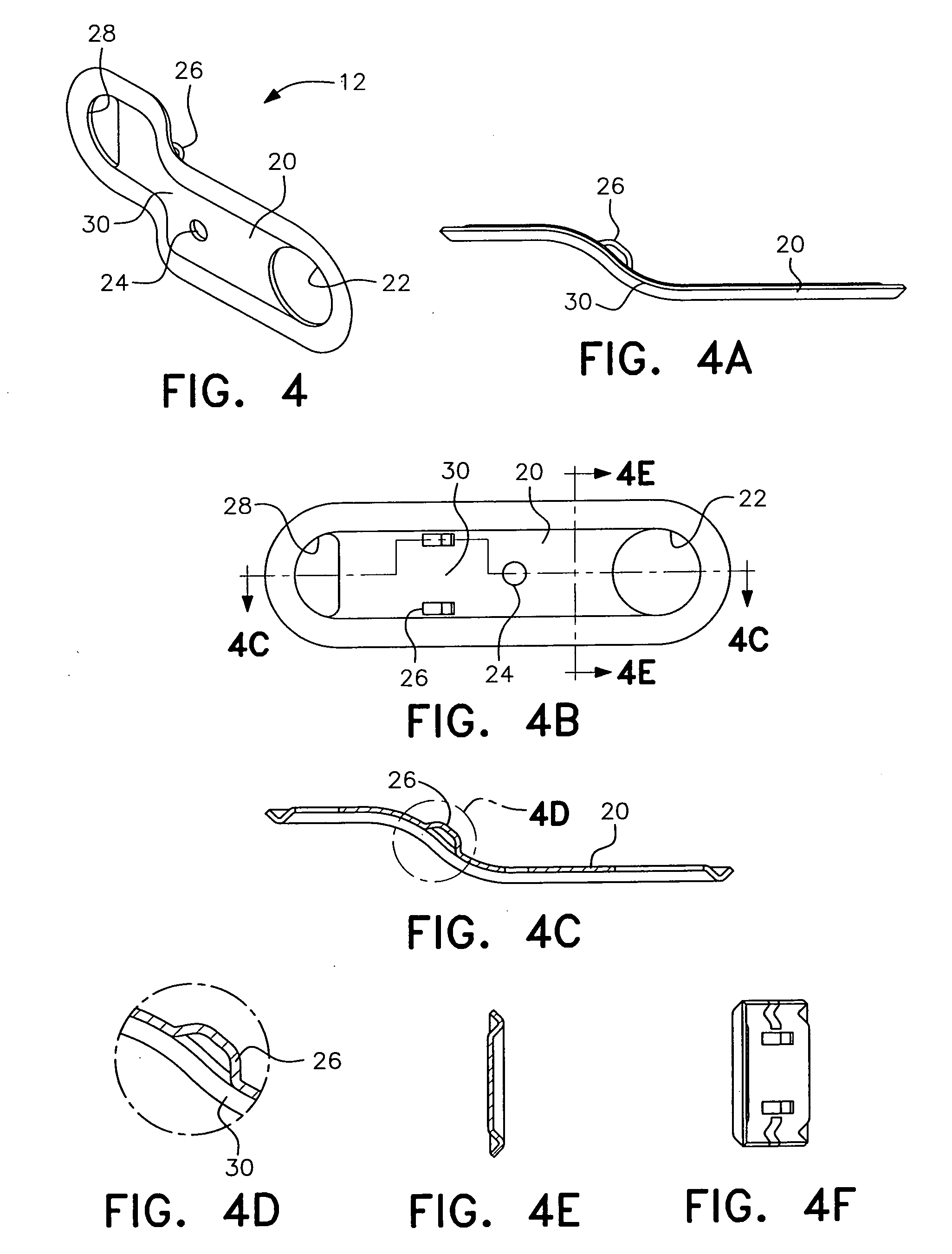
[0091]The strap 12 can be a unified member or, as shown in FIGS. 3, 4 and 4A-4F, may be comprised of two separate strap members 12a and 12b that are connected to one another when the strainer is assembled as shown in FIG. 2. The two strap members are identical which facilitates ease of manufacture, with each strap member having a body 20 with an axle mounting aperture 22, a pawl mounting aperture 24, a pair of pawl spring mounting loops 26, an...

fifth embodiment

[0114]the torque limiting mechanism in accordance with the present invention is illustrated in FIGS. 23-25 and generally designated by reference numeral 500. A compression spring 552 is sandwiched between two pressure plates 553 and secured within the hollow central portion 540 of the reel by nuts 550. The pressure plates 553 are provided with peripheral detents 554 that engage corresponding notches 544 in the reel inner wall 542. A shoulder screw 557 is inserted through aligned apertures 559 in the pressure plates 553 and twisted to compress the spring 552. Upon sufficient compression of the spring, the detents 554 on the pressure plates will disengage from the reel notches 544 in a manner similar to the previous embodiments.

sixth embodiment

[0115]the torque limiting mechanism according to the present invention is illustrated in FIGS. 26-28 and generally designated by reference numeral 600. In this embodiment, the axle is formed by two nuts 650 which serve as the tool engagement heads on either side of the reel 614. A urethane spring 652 is inserted into the bore 651 of each of the nuts 650 and then tightened to the desired degree with a respective shoulder screw 657. The nuts 650 are rotated to turn the reel 614 and tension the wire until the springs 652 exceed the frictional forces preventing rotation and allow “slip” within the bores.

[0116]A seventh embodiment of the torque limiting mechanism in accordance with the present invention is illustrated in FIGS. 29-31 and generally designated by reference numeral 700. This embodiment operates similarly to the sixth embodiment, except that the axle does not go all the way through the reel 714. Belleville springs 752 are compressed by shoulder screw 757 until interference su...


PUM


Abstract

An in-line strainer for placement within a span of wire fence to apply tension thereto is provided. The in-line strainer includes a reel having a hollow central hub for receiving a torque limiting mechanism. The torque limiting mechanism includes a central axle and a spring mechanism. As the axle is manually rotated, the reel is also rotated through its engagement with the torque limiting mechanism until a target tension on the wire is reached. Once the target tension has been reached, the torque limiting mechanism disengages, allowing the axle to “slip” relative to the reel, preventing further rotation of the reel and, consequently, further tensioning of the wire. In addition, the in-line strainer includes a failure mechanism which ensures that, when the load threshold on the fence is exceeded, the in-line strainer will automatically release tension on the wire wound thereon in a predictable and safe manner.

Description

BACKGROUND OF THE INVENTION[0001]1. Field of the Invention[0002]The present invention is related to wire fencing and, more particularly, to a device for controlling maximum tension during installation of high tensile wire fence and for providing a predictable release mechanism when tension overload occurs.[0003]2. Description of the Related Art[0004]When installing high tensile wire fence, such as for livestock, it is necessary to place a specified amount of tension on the wire. Typically, this tension is applied after the wire has been strung around a fence perimeter by installing an in-line strainer at spaced locations along spans of fencing. A representative conventional in-line strainer installed on a wire extending between two fence posts is shown in FIG. 1. The use of in-line strainers to tension wire fencing is well known in the art.[0005]A commonly recommended pre-load for high tensile fences is 250 lb of tension. To set the pre-tension of the wire, existing in-line strainer...

Claims


Application Information

Patent Timeline
IPC IPC(8): E04H17/06E04H17/26
CPCF16G11/12E04H17/266E04H17/133
Inventor MOORE, MACK THOMASLUBIC, MARKO KONSTANTIN
Owner WOODSTREAM CORP
Why Eureka
Try Eureka