
Taut Wire Fence System

a technology of wire fence and wire fence, which is applied in the direction of burglar alarm mechanical actuation, instruments, force/torque/work measurement apparatus, etc., can solve the problems of reducing the sensitivity of the sensor to a change in tension, the device to be mounted on the support post cannot detect tampering activities through electrical disturbance,

Active Publication Date: 2012-06-07
GALLAGHER ELECTRONICS LTD CO
View PDF5 Cites 8 Cited by
  • Summary
  • Abstract
  • Description
  • Claims
  • Application Information

AI Technical Summary

Benefits of technology

[0058]The main body member may be formed from a single material, or may have different portions formed from different materials. For example, some portion of the main body may be formed from a plastics material. This may be done for example to save cost, or to reduce the weight of the main body. When the connector is used with an electric fence system different materials may be used to insulate the main body of the connector and the sensor system from the high voltage of the electrified wire and to provide insulation between an end support post and the wire.
[0104]the ability to re-tension a wire of the fence system without the need to disengage the connector or otherwise disassembly the fence system; and

Problems solved by technology

This can result in the fence wires deflecting downwards and connecting together as a short circuit which can be detected as loss or reduction of electrical signal through a wire.
However, in many instances a taut wire fence is not an electric fence and hence tamper activities cannot be detected through an electrical disturbance as with an electric fence.
However, this system has a number of disadvantages, including the requirement for the device to be mounted onto a support post.
Not all taut wire fence systems include intermediate support posts.
A further disadvantage is that the sensitivity of the sensor to a change in tension can change (decrease quite rapidly) as the plate member pivots.
A further disadvantage with the system disclosed by Buckley et al. is that it is configured to detect a change in deflection of one or other of the wires, causing the plate member to pivot, rather than the tension itself.
The device of Buckley can also create problems if for any reason the fence requires re-tensioning, as may be required from time to time for maintenance of the taut wire fence.
Either way, this process can take more time than is normally required to re-tension a fence wire.
A disadvantage with this type of device is that they can be readily circumvented.
It is also not clear how the devices would perform if one or other of the connected wires were cut.
Further, the devices are not configured to measure the actual tension in the wires or how this may change over time, and therefore cannot provide information relating to the condition of the fence at all times. In particular, they are generally unable to detect the different characteristics of an attempt to tamper with the fence and a change in tension due to other events, such as an animal pushing against the wires.
As both can lead to changes in tension, these devices are prone to providing false alarms (i.e. alarms raised due to events other than human tampering),
One common problem with each of these devices is that the sensor or tensile force gauge does not measure the tension in the wire directly, but rather the balance of the tensions on either side of the micro switch or tensile force gauge.
As a result, this arrangement cannot detect a change in tension by the same amount on both sides of the switch or gauge.
Such changes can occur over time due to stretching of the wire or temperature variations for example, in each case reducing the effectiveness of the taut wire fence and the detection devices.
A sensor / gauge system of the prior art devices discussed above cannot detect an overall change in the tension, for whatever reason, which can result in the tension dropping below the desired range without activation of an alarm.
If the wire of the fence becomes sufficiently loose over time the sensor / gauge may not detect further deflection due to tampering.
A further problem with these systems is that they can be prone to false alarms.
Such systems cannot differentiate between a tension change due to a deliberate attempt to tamper, and, for example, an accidental change due to an animal pushing against the wire.
Another problem with these arrangements in general is that the wire(s) cannot be re-tensioned without disconnecting the detector from the wire.
This can add time and cost to maintenance and is generally inconvenient.
Another problem is the high cost of installation of the sensors and the large number of them required when they are attached to each support post and each wire of a security fence system.

Method used


Image

  • Taut Wire Fence System
  • Taut Wire Fence System
  • Taut Wire Fence System

Examples


Embodiment Construction

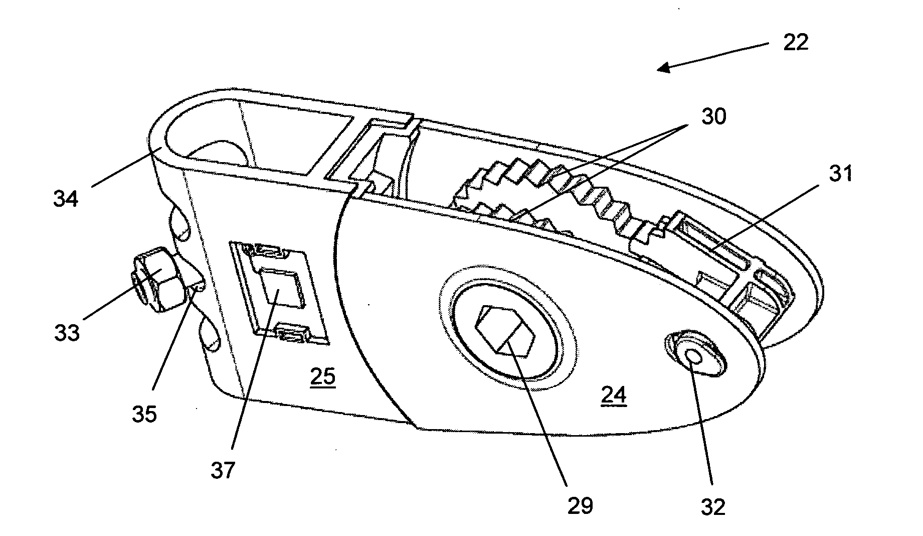
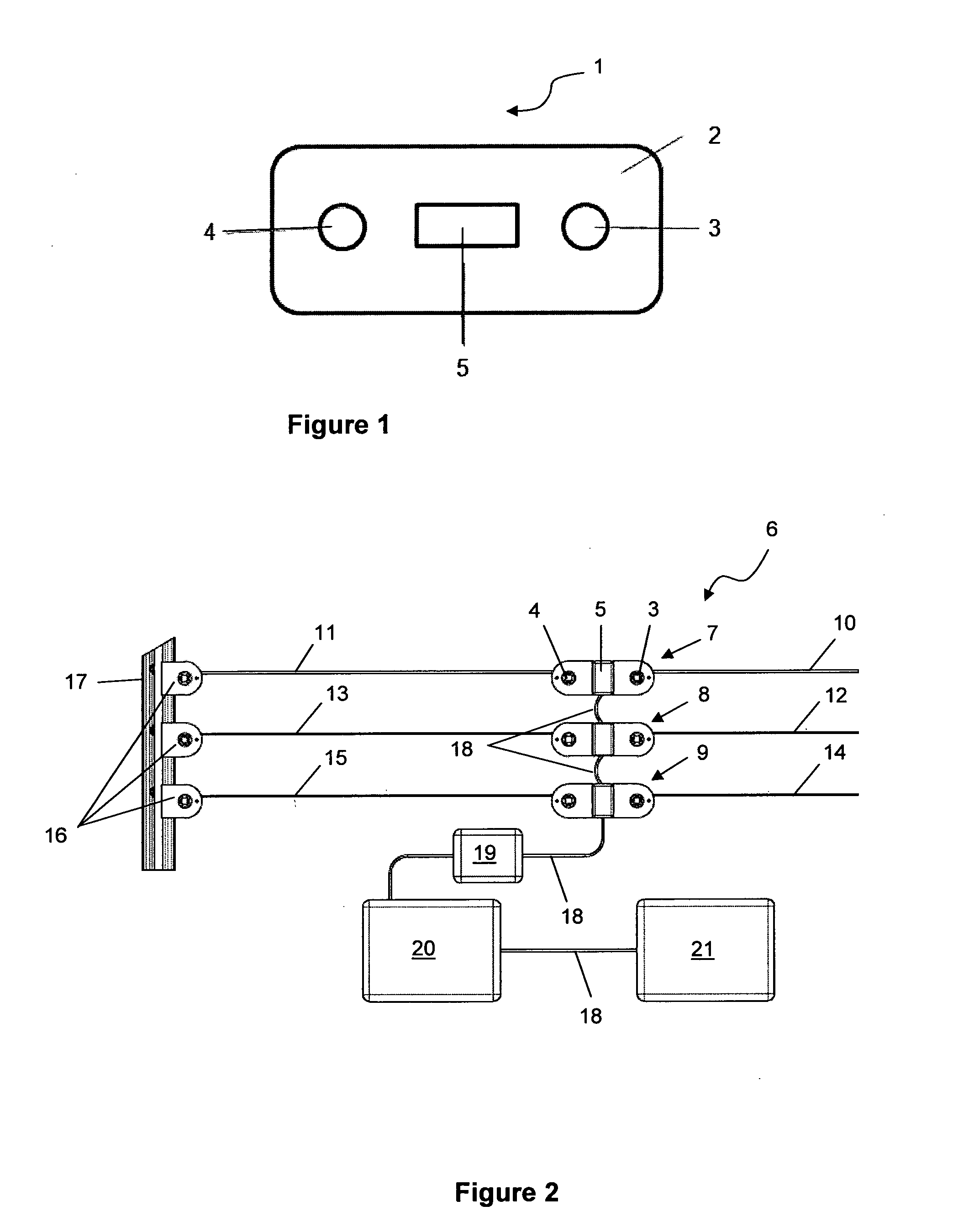
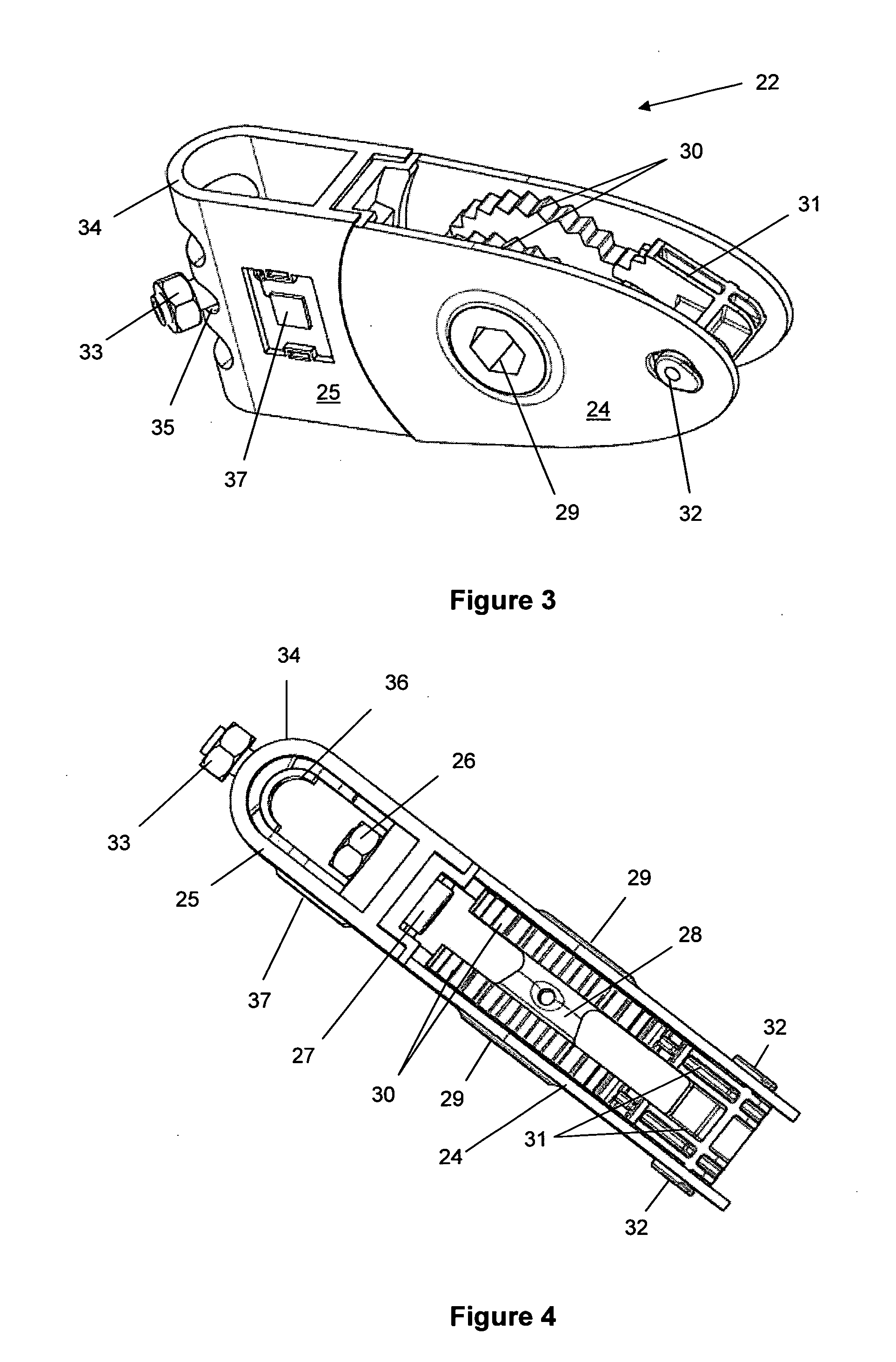
[0116]A connector according to one embodiment of the present invention is generally indicated by arrow one in FIG. 1. The connector 1 includes a main body member 2 which is formed as a single member from a rigid plastics material such as high density polyethylene or polyester, or a glass filled nylon material.

[0117]The main body member 2 includes a first engagement proportion 3 configured to attach to a wire (not shown) of a taught wire fence and a second engagement portion of 4 also configured to attach to a wire of the taught body fence system (not shown). When used with an electric fence system the first and second engagement portions (3 and 4) are automatically electrically insulated from the plastic main body member 2.

[0118]A sensor, 5, including a thick film resistor paste strip mounted on a metal plate which is firmly attached to the main body member 2, is located between the first (3) and second (4) engaging portions such that the first engagement portion (3), the sensor 5 a...


PUM

PropertyMeasurementUnit
Temperatureaaaaaaaaaa
Forceaaaaaaaaaa
Dimensionaaaaaaaaaa

Abstract

An apparatus and method of detecting a change in tension of a taut wire fence system, where the system includes a connector including a main body member having a first attachment portion at one end of the member and a second attachment portion at the opposite end of the member and a sensor located on the main body between and aligned with the first and second attachment portions, the method including the steps of attaching a first wire of the fence to the first attachment portion and attaching the second attachment portion of the connector either to an end support mount for the fence, or to a second wire of the fence system such that the connector is held independently of direct contact with any fence support, and such that the first wire, the sensor on the main body of the connector and the second attachment portion respectively, are aligned.

Description

STATEMENT OF CORRESPONDING APPLICATIONS[0001]This application is based on the Provisional Specification filed in relation to New Zealand Patent Application Number 573055, the entire contents of which are incorporated herein by reference.TECHNICAL FIELD[0002]The present invention relates to a method and system for use with taut wire security fence applications, and in particular, although not limited to, a system or method of sensing when there is an attempt to breach or tamper with a taut wire security fence.BACKGROUND ART[0003]Fence systems that are capable of sensing tamper related activity on the fence wire are well known in the containment and security industries. A taut wire security fence system is one in which one or more wires are held in tension between two end supports. An end support may be any support where the wire of the fence is terminated, such as at a fixed post or another fixed physical structure (for example, a wall). A taut wire fence may include a number of inte...

Claims


Application Information

Patent Timeline
IPC IPC(8): E04H17/10B23P6/00G01B21/02G06F19/00G01L5/04
CPCA01K3/00Y10T29/49718A01K3/005H01H3/02E04H17/06G08B13/12
Inventor GALLAGHER, IAN STUART
Owner GALLAGHER ELECTRONICS LTD CO
Learn More