Wind power generator and yaw bearing replacement method for a wind power generator

a wind power generator and yaw bearing technology, which is applied in the direction of electric generator control, machines/engines, final product manufacturing, etc., can solve the problems of large crane cost, large cost of yaw bearing itself, and other costs related to the cost of yaw bearing, etc., to achieve the effect of simple devi

Inactive Publication Date: 2012-06-07
HITACHI LTD
View PDF3 Cites 10 Cited by
  • Summary
  • Abstract
  • Description
  • Claims
  • Application Information

AI Technical Summary

Benefits of technology

[0009]The object of the present invention is to provide a wind power generator and yaw bearing replacement method for a wind power generator that make it possible to replace the yaw bearing using a simple device.

Problems solved by technology

However, in that case, the cost of the large crane, the cost of labor, the cost of preparing the ground in order to locate the crane and the like, as well as other costs related to the cost of the yaw bearing itself becomes very large.
However, by using the conventional technology described above, it is difficult to replace the yaw bearing from the installation position of the bearing, and technology is desired that would allow the replacement of the yaw bearing without the use of a large crane.

Method used


Image

  • Wind power generator and yaw bearing replacement method for a wind power generator
  • Wind power generator and yaw bearing replacement method for a wind power generator
  • Wind power generator and yaw bearing replacement method for a wind power generator

Examples


embodiment 1

[0047]In the following a first embodiment of a wind power generator and yaw bearing replacement method for that wind power generator to which the present invention is applied is explained.

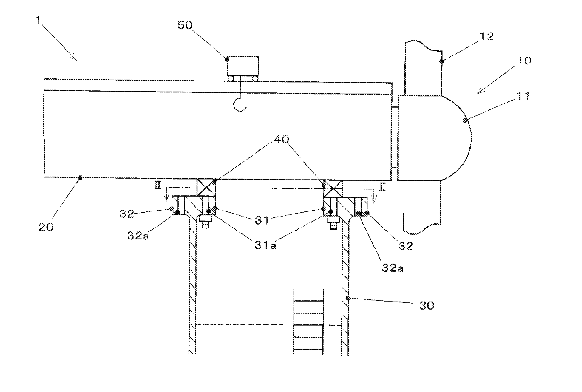
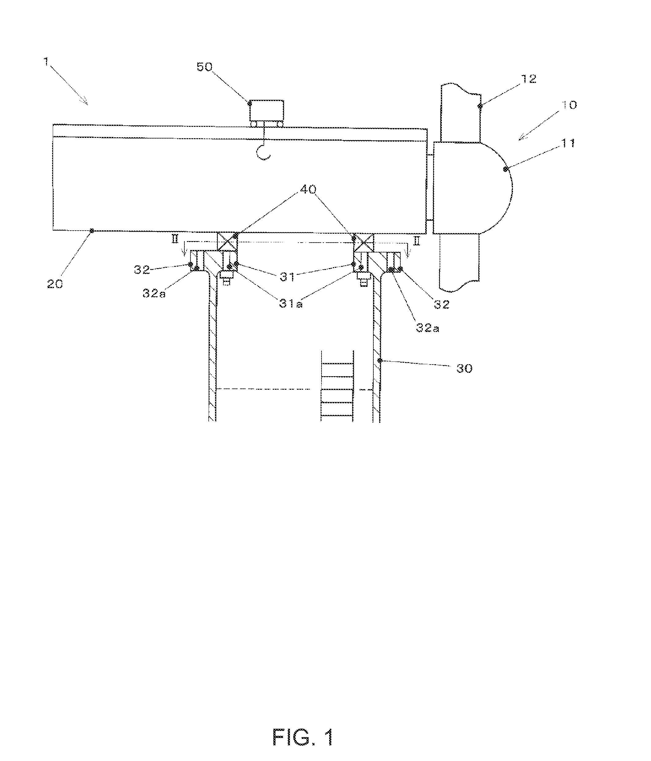
[0048]FIG. 1 is a schematic cross-sectional view of the connecting section between the nacelle and tower of a wind power generator. The wind power generator 1 comprises a rotor 10, nacelle 20, tower 30, yaw bearing 40 and crane 50.

[0049]The rotor 10 is a wind turbine that rotates by receiving the force of the wind, and comprises a hub 11 and blades 12.

[0050]The hub 11 is provided in the center section of the rotor 10, and is supported by a bearing (not illustrated in the figures) such that it can rotate around a nearly horizontally placed axle.

[0051]A plurality of blades 12 are arranged such that they radially extend from the hub 11, and each blade has an airfoil section that generates torque by receiving the force of the wind.

[0052]The nacelle 20 is the portion that houses a generator that is rota...

embodiment 2

[0066]Next, a second embodiment of a wind power generator and yaw bearing replacement method for that wind power generator to which the present invention is applied is explained. The same reference numbers will be assigned to locations that are essentially in common with those of the first embodiment described above, and any redundant explanation will be omitted, so that the explanation below centers on mainly the differences. FIG. 4 and FIG. 5 are enlarged schematic perspective views of the connecting section between the nacelle and the tower, where FIG. 4 illustrates the state during normal use, and FIG. 5 illustrates the state during yaw bearing replacement (replacement of the drive device and jig).

[0067]As illustrated in FIG. 4, a drive device installation section 21 is provided in the nacelle 20. The drive device installation section 21 is a flat member that horizontally protrudes toward the outside in the radial direction of the yaw bearing 40, and openings 21a are formed in t...


PUM


Abstract

The object of the invention is to provide a wind power generator whose yaw bearing can be replaced by a simple device. A wind power generator has a nacelle, a tower that supports the nacelle at a high location, a yaw bearing that is located between a first bearing seat that is provided on the bottom section of the nacelle and a second bearing seat that is provided on the top section of the tower, first and second jack seats that extend to the outer diameter side of the first and second bearing seats, a jack-up unit that is located between the first and second jack seats so that there is a space though which the yaw bearing can be removed or installed in the radial direction of the yaw bearing, and that can jack up the nacelle, and a suspension unit that is provided on the nacelle and that can move while suspending the yaw bearing.

Description

CROSS REFERENCE TO RELATED APPLICATIONS[0001]This application claims priority under 35 U.S.C. 119 based upon Japanese Patent Application Serial No. 2010-271292, filed on Dec. 6, 2010. The entire disclosures of the aforesaid applications are incorporated herein by reference.FIELD OF THE INVENTION[0002]The present invention relates to a wind power generator and a yaw bearing replacement method for a wind power generator, and more particularly to those which make replacement of the yaw bearing possible with a simple device.BACKGROUND OF THE INVENTION[0003]A wind power generator comprises a generator located inside a nacelle that is supported in a high place by a tower, with the generator being driven by a rotor. A yaw bearing is provided between the nacelle and tower, and supports the nacelle such that the nacelle can rotate in the yaw direction.[0004]Conventionally, when such a yaw bearing became broken for some reason and required replacement, a large crane or the like was used to re...

Claims


Application Information

Patent Timeline
Patent Type & Authority Applications(United States)
IPC IPC(8): F03D11/04
CPCF03D1/003F05B2230/61F05B2230/70F05B2230/80F03D11/04F05B2240/916Y02E10/726Y02E10/728F05B2240/50F03D13/20F03D80/50F03D80/70F03D13/40F03D9/25Y02E10/72Y02P70/50
Inventor TOBINAGA, IKUO
Owner HITACHI LTD
Why Eureka
Try Eureka