Gate-Based Output Power Level Control Power Amplifier

a power amplifier and gate technology, applied in amplifiers, amplifiers with semiconductor devices/discharge tubes, amplifiers, etc., can solve the problems of high cost, large size and cost of directional couplers, and the solution is difficult to meet the demanding and continuous cost reduction of consumer products market,

Active Publication Date: 2012-06-07
QORVO INT PTE LTD
View PDF8 Cites 19 Cited by
  • Summary
  • Abstract
  • Description
  • Claims
  • Application Information

AI Technical Summary

Problems solved by technology

The main drawback of the directional coupler based power control is its very large size and cost due to the directional coupler.
Such a solution has hard time of meeting the demanding and continuous cost reduction of the consumer products market.
Such resistance needs also to pass the high current, hence a high cost.
The main drawback of this regulator, or alternatively DC-DC converter supply modulation or drain power control technique, is its large area and thus cost, brought by a very large power control device that is connected in series with the high current high power output signal path.
As mentioned before, the main drawback of this technique is that the power control block 130 is placed in the path of the high value output current and therefore the power control devices connected in series with the PA 114 need to be very large, impacting cost.
Furthermore, placing the power control block in series with the high current path results in power losses, and thus efficiency degradation.
Since PA 114 usually operates most of the time at power levels lower than the peak rated power, the degraded efficiency of backed-off power levels results usually in a lower talk time as a given battery charge.

Method used


Image

  • Gate-Based Output Power Level Control Power Amplifier
  • Gate-Based Output Power Level Control Power Amplifier
  • Gate-Based Output Power Level Control Power Amplifier

Examples


Embodiment Construction

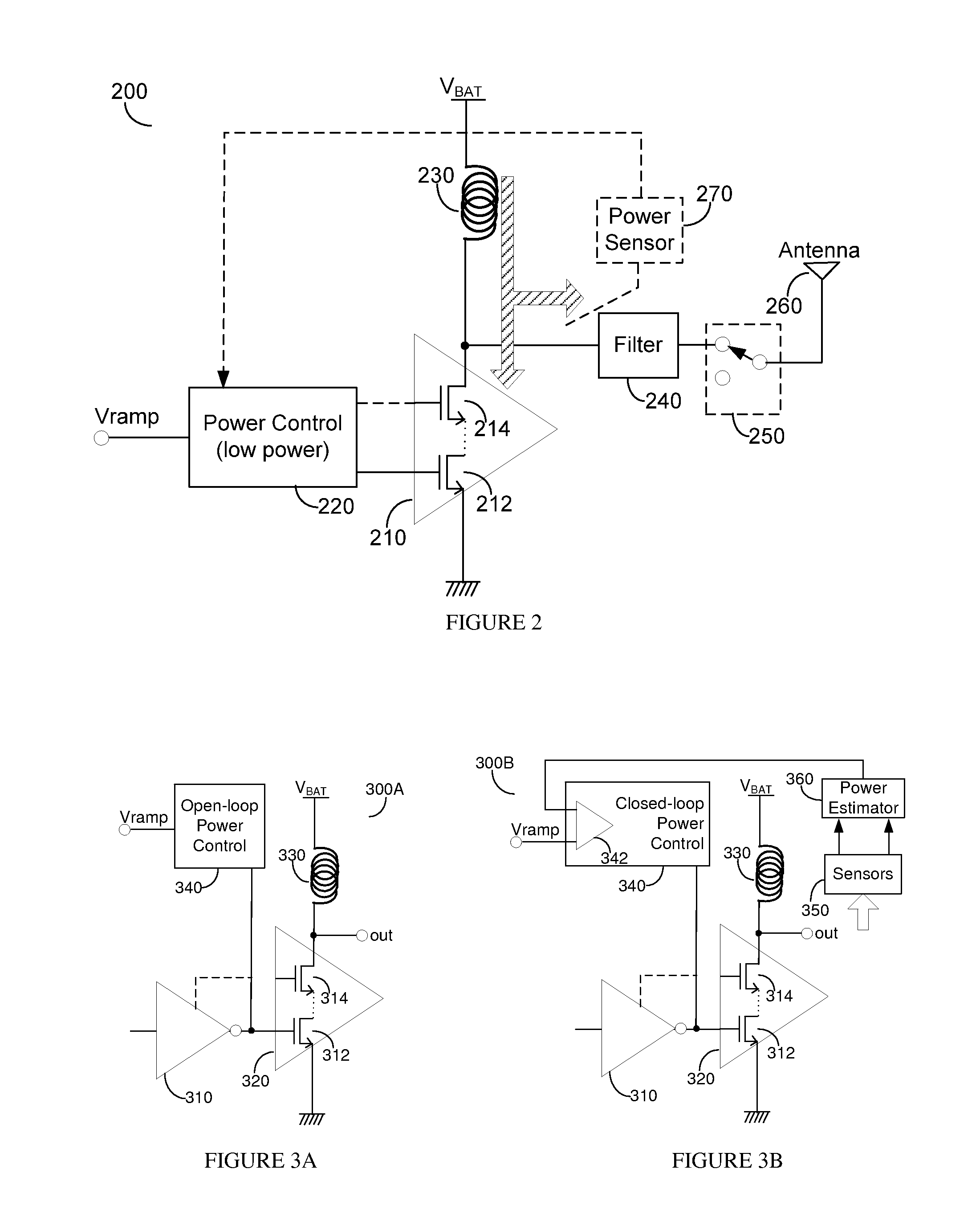
[0031]A gate power control technique for a power amplifier (PA) provides practical improved efficiency at backed-off power levels. It can be applied to the main gate of the output stage of the PA, the cascode gate, or any combination thereof. Both voltage mode and current mode signal processing may be used. The gate power control can be implemented in both open-loop and closed-loop using AC and DC coupled drivers and output stages. It may further use one or more control ports in the radio frequency (RF) signal path.

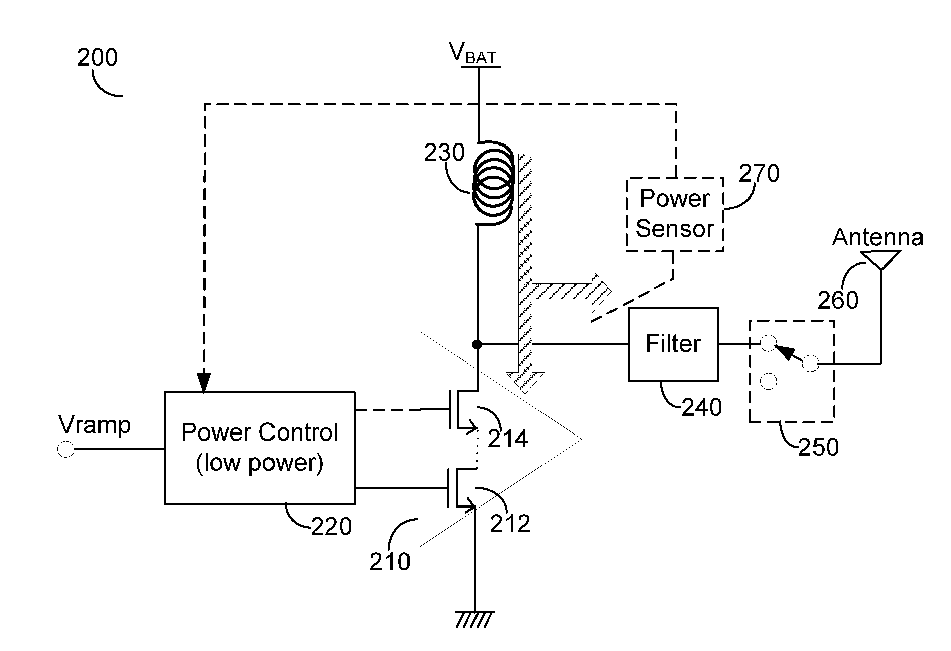
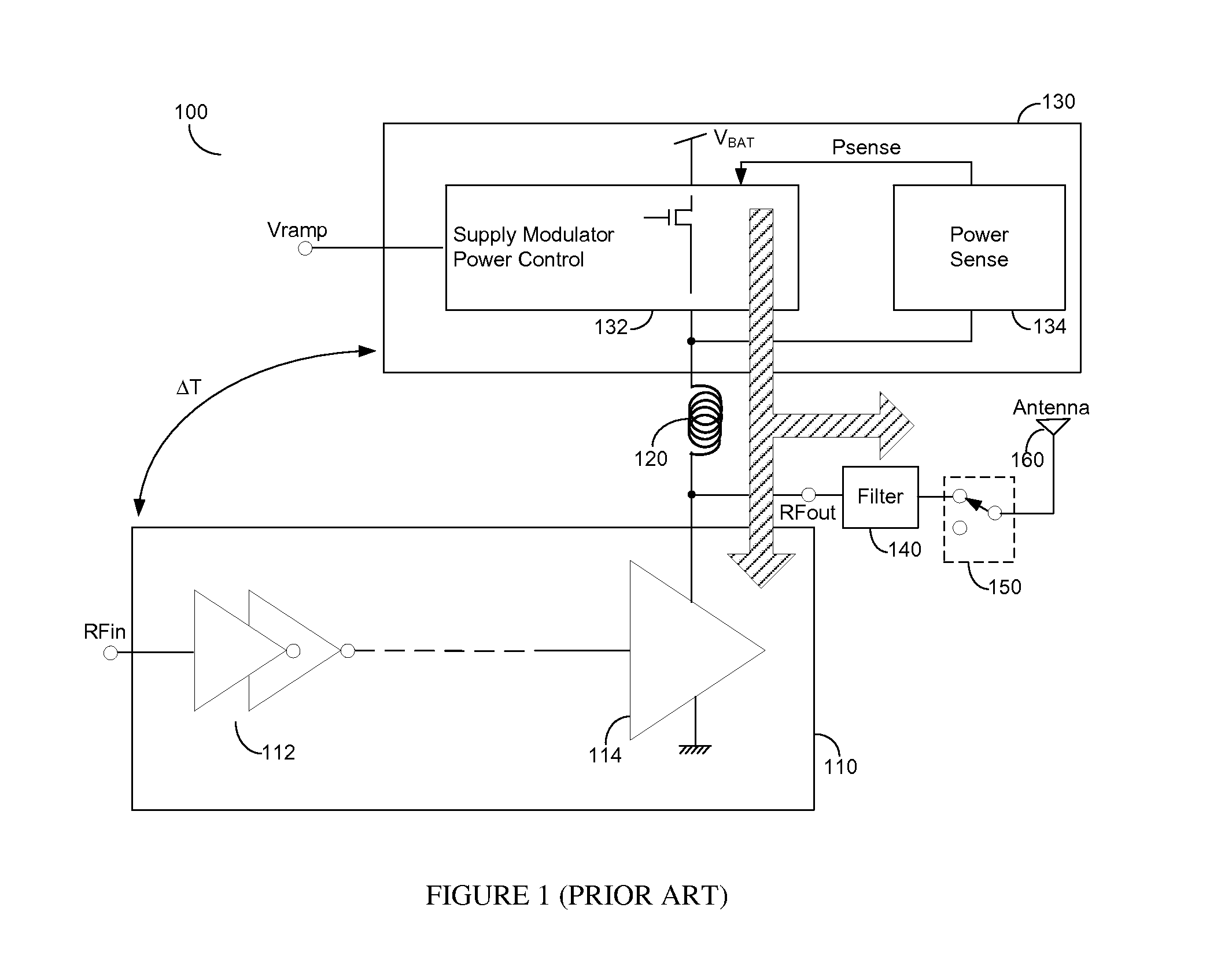
[0032]Reducing the size and cost of PA systems requires the elimination of the larger supply modulation block needed for the drain (collector) power control. The key idea of this invention is to move the power control block out of the high output current path and to a low current node, as shown in the exemplary and non-limiting FIG. 2. The power control block 220 provides the DC operating conditions of the main gate 212 of the metal-oxide semiconductor (MOS) output stage ...


PUM


Abstract

A gate power control technique for a power amplifier (PA) provides practical improved efficiency at backed-off power levels. It can be applied to the main gate of the output stage of the PA, the cascode gate, or any combination thereof. Both voltage mode and current mode signal processing may be used. The gate power control can be implemented in both open-loop and closed-loop using AC and DC coupled drivers and output stages. It may further use one or more control ports in the radio frequency (RF) signal path.

Description

CROSS-REFERENCE TO RELATED APPLICATIONS[0001]This application claims the benefit of U.S. Provisional Patent Application No. 61 / 419,860 filed Dec. 5, 2010.BACKGROUND OF THE INVENTION[0002]1. Field of the Invention[0003]The invention generally relates to power amplifier output power level control and more specifically to power control of the output power amplifier of a power amplifier system by its input gate.[0004]2. Prior Art[0005]Power amplifiers for constant envelope signal modulation application require a mechanism for regulating their output power level based on an input signal (Vramp) provided by the transmit block. One possibility is that the output power is sensed by a directional coupler followed by a radio frequency (RF) power detector. A feedback loop is locked around the PA by comparing the targeted power level Vramp with the sensed power level Psense. The error signal provided by the error amplifier is sent to the power control block which generates one or more control s...

Claims


Application Information

Patent Timeline
Patent Type & Authority Applications(United States)
IPC IPC(8): H03G3/00
CPCH03G1/007H03G3/3042H03F1/0233H03F1/0261H03F2200/465H03F3/245H03F2200/18H03F2200/405H03F1/223
Inventor HO, DANIELFRANCK, STEPHENSHI, YINGSCOTT, BAKER
Owner QORVO INT PTE LTD
Why Eureka
Try Eureka