Light source device and projection display apparatus

a technology of projection display and light source device, which is applied in the direction of lighting and heating apparatus, instruments, optics, etc., can solve the problems of low reliability and difficulty in obtaining a high brightness, and achieve the effect of high efficiency

Active Publication Date: 2012-06-07
PANASONIC CORP
View PDF1 Cites 92 Cited by
  • Summary
  • Abstract
  • Description
  • Claims
  • Application Information

AI Technical Summary

Benefits of technology

[0007]The present invention aims to provide a light source device that condenses efficiently lights from a large number of solid-state light sources and has a high spectrum utilization factor of light emission obtained by exciting a phosphor.
[0012]According to the present invention, since the polarization direction of light exiting from the solid-state light source is converted by a retardation plate arranged between the solid-state light source unit and the dichroic mirror, the light quantity ratio of fluorescence emitted by the fluorescence emission plate to a light from the solid-state light source is adjusted to be optimum, and thus a light source device of a high efficiency can be provided.
[0013]Further, by use of a light source device of the present invention, a long-life and bright projection display apparatus can be obtained.

Problems solved by technology

However, the problem of such a discharge lamp is the low reliability due to the short life.
Therefore, it is difficult to obtain a high brightness with the configuration as illustrated in FIG. 8.

Method used


Image

  • Light source device and projection display apparatus
  • Light source device and projection display apparatus
  • Light source device and projection display apparatus

Examples


embodiment 1

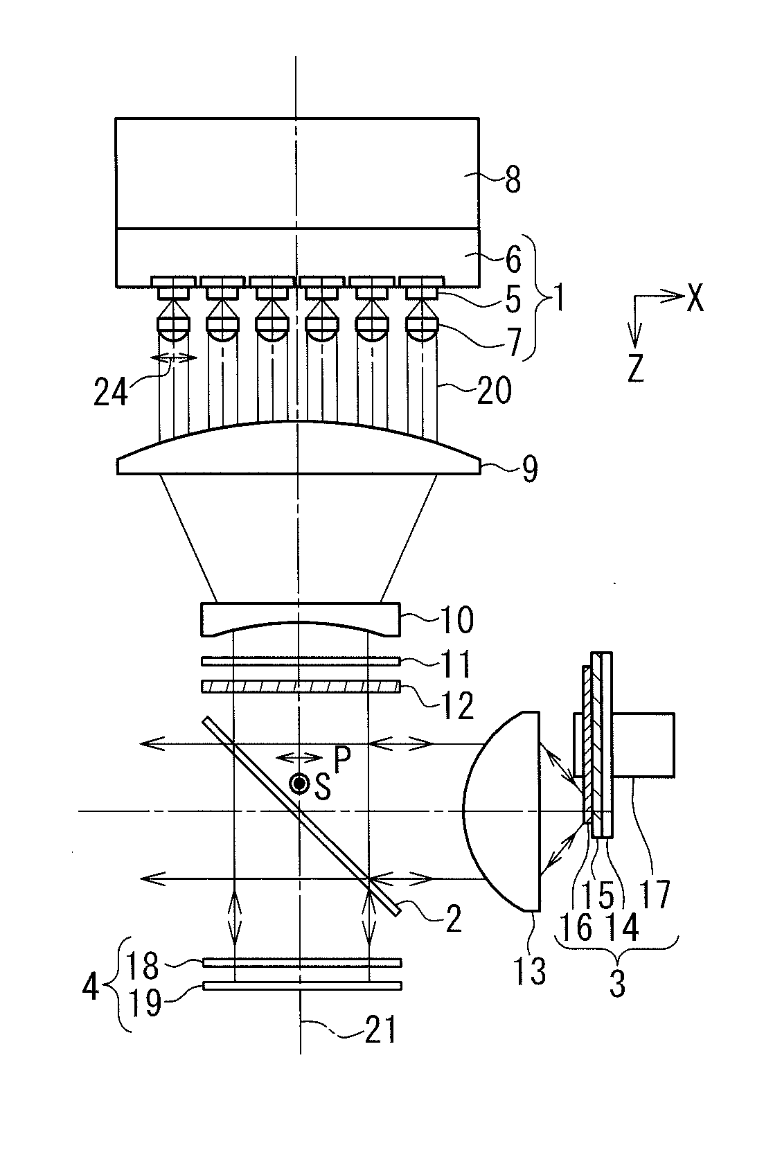
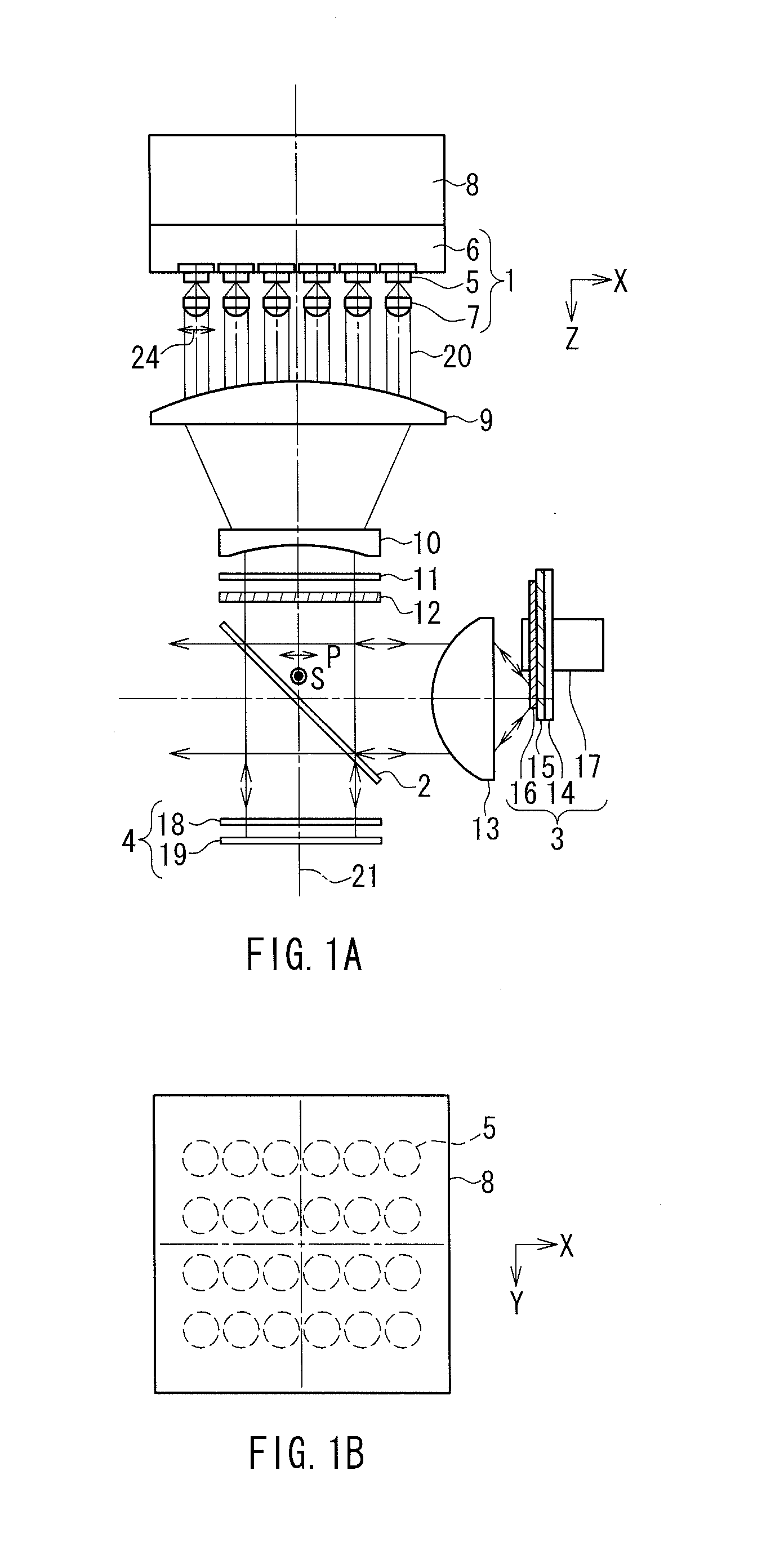
[0037]FIG. 1A is a front view showing a configuration of a light source device according to Embodiment 1 of the present invention. This light source device includes as basic elements a solid-state light source unit 1, a dichroic mirror 2, a fluorescence emission plate 3 and a polarization direction converting portion 4. The dichroic mirror 2 polarization separates the incident light by reflecting the s-polarization component and transmitting the p-polarization component. The fluorescence emission plate 3 is excited with the s-polarization component and emits fluorescence. The p-polarization component is converted into the s-polarization component by the polarization direction converting portion 4 and reflected by the dichroic mirror 2. Thereby, a color light from the fluorescence emission plate 3 and a color light from the polarization direction converting portion 4 are combined at the dichroic mirror 2 and exit there.

[0038]The solid-state light source unit 1 has semiconductor laser...

embodiment 2

[0053]FIG. 5 is a front view showing a configuration of a light source device in Embodiment 2 of the present invention. This light source device is different from the light source device in Embodiment 1 in that the blue color light to be combined for obtaining a white color light is not a light exiting from the semiconductor laser 5 but a blue color light from a light-emitting diode. Except for some elements modified for this reason, the constructions of the elements such as the solid-state light source unit 1 and the fluorescence emission plate 3 are the same as those in Embodiment 1, and thus common elements are assigned with the same reference numbers in order to avoid duplicated explanation.

[0054]In FIG. 5, the half wave plate 25 and the dichroic mirror 26 correspond to the half wave plate 12 and the dichroic mirror 2 in FIG. 1A. However, the half wave plate 25 is configured to rotate the polarization direction of the linearly polarized light by about 90 degrees. Further, a blue...

embodiment 3

[0060]FIG. 7 shows a projection display apparatus in Embodiment 3 of the present invention. This projection display apparatus is constructed by using the light source device according to Embodiment 1. Therefore, common elements are assigned with the same reference numbers as in Embodiment 1 in order to avoid duplicated explanation.

[0061]In the present embodiment, a TN mode or a VA mode transmission type liquid crystal panel of an active matrix system, having a thin film transistor formed on the pixel region, is used for the light valve.

[0062]An illuminating portion that condenses the light exiting from the dichroic mirror 2 of the light source device so as to form an illumination light is constituted of a first and second lens array plates 30, 31, a polarization converting optical element 32, and a superimposing lens 33. A color-separating portion for color-separating the illumination light that has passed through the superimposing lens 53 and making the lights enter the liquid crys...


PUM


Abstract

A light source device has: a light source unit including solid-state light sources emitting blue-color light and a condensing lens; a dichroic mirror polarization separating color light into first and second polarization components; a fluorescence emission plate excited with the first polarization component, emitting fluorescence of green and red components to enter the dichroic mirror; a first retardation plate converting the second polarization component to a circularly polarized light; and a reflection plate reflecting a light passed through the first retardation plate to reenter the same. The color lights from the fluorescence emission plate and the first retardation plate are combined at the dichroic mirror. A second retardation plate converts the polarization direction of the light from the light source unit, so as to control the ratio of p-polarization and s-polarization components. Lights from solid-state light sources are condensed efficiently and a high spectrum-utilization factor is obtained.

Description

BACKGROUND OF THE INVENTION[0001]1. Field of the Invention[0002]The present invention relates to a light source device using fluorescence obtained by condensing lights from a number of solid-state light sources and exciting a phosphor, and a projection display apparatus using the light source device.[0003]2. Description of Related Art[0004]Discharge lamps have been used widely as light sources for projection display apparatuses using light valves formed of liquid crystals or a mirror-deflection type digital micro-mirror devices (DMD). However, the problem of such a discharge lamp is the low reliability due to the short life. For solving this problem, a projection display apparatus, which uses a solid-state light source such as a semiconductor laser and a light-emitting diode for the light source in place of the discharge lamp, has been studied.[0005]FIG. 8 shows a configuration disclosed in JP 2004-341105 A as an example of a conventional projection display apparatus using a solid-s...

Claims


Application Information

Patent Timeline
Patent Type & Authority Applications(United States)
IPC IPC(8): G03B21/14F21V9/14
CPCG03B21/14G03B21/28G03B33/12G03B21/2073G03B21/204
Inventor TANAKA, TAKAAKIKITANO, HIROSHI
Owner PANASONIC CORP
Why Eureka
Try Eureka