
Printing apparatus, data storage method, and program

Inactive Publication Date: 2012-06-07
CANON KK
View PDF2 Cites 9 Cited by
  • Summary
  • Abstract
  • Description
  • Claims
  • Application Information

AI Technical Summary

Benefits of technology

[0009]One disclosed aspect of the embodiments is directed to preventing as much as possible cases in which a user's own print data are not able to be selected when executing reprint processing, even when the capacity of a secondary storage device is low.
[0011]According to the embodiments, cases in which a user's own print data are not able to be selected when executing reprint processing may be prevented as much as possible, even when the capacity of a secondary storage device is low.

Problems solved by technology

In contrast, unlike the BOX storage function, a reprint function does not guarantee the print data in the data storage area, and may only reprint the print data that may be stored in the data storage area.
However, in the reprint function, based on the remaining capacity of the secondary storage device, old print data may be deleted without a user trigger if the newest print data are not able to be stored.
However, considering the environment that SFPs are used in the recent office, cases in which a small number of SFPs are shared by a large number of users via a network may occur.
In this case, despite the fact that a user has only input one piece of print data, depending on the subsequent print data input situation by other users and the size of the print data, there is an issue that even if the user tries to reprint the one piece of print data, the print data may not even be selected because the user's own data has already been deleted from the data storage area.
Therefore, this technique does not overcome the above issue that occurs when executing reprint processing.
Therefore, this technique also does not overcome the above issue that occurs when executing reprint processing.

Method used


Image

  • Printing apparatus, data storage method, and program
  • Printing apparatus, data storage method, and program
  • Printing apparatus, data storage method, and program

Examples


Embodiment Construction

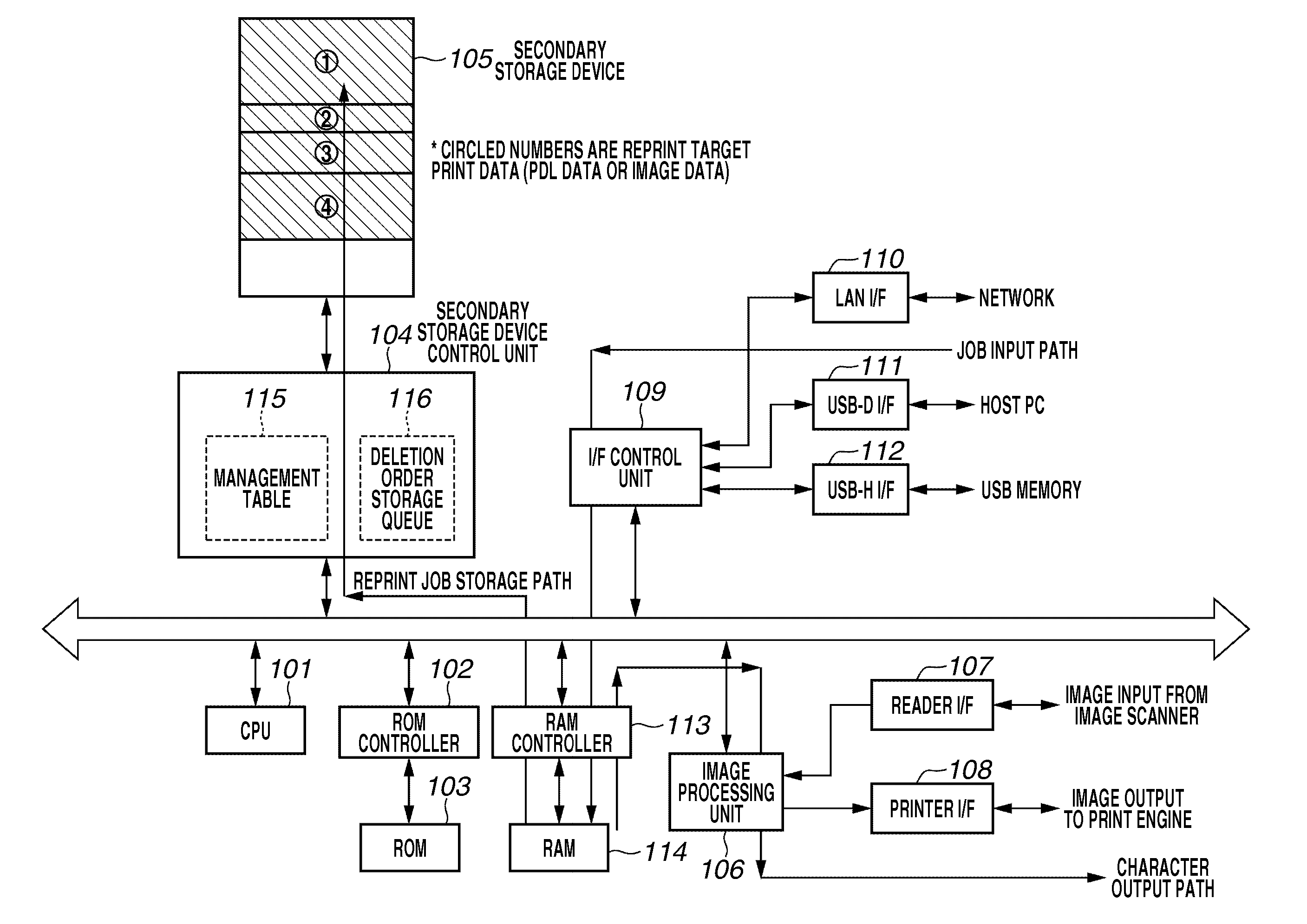
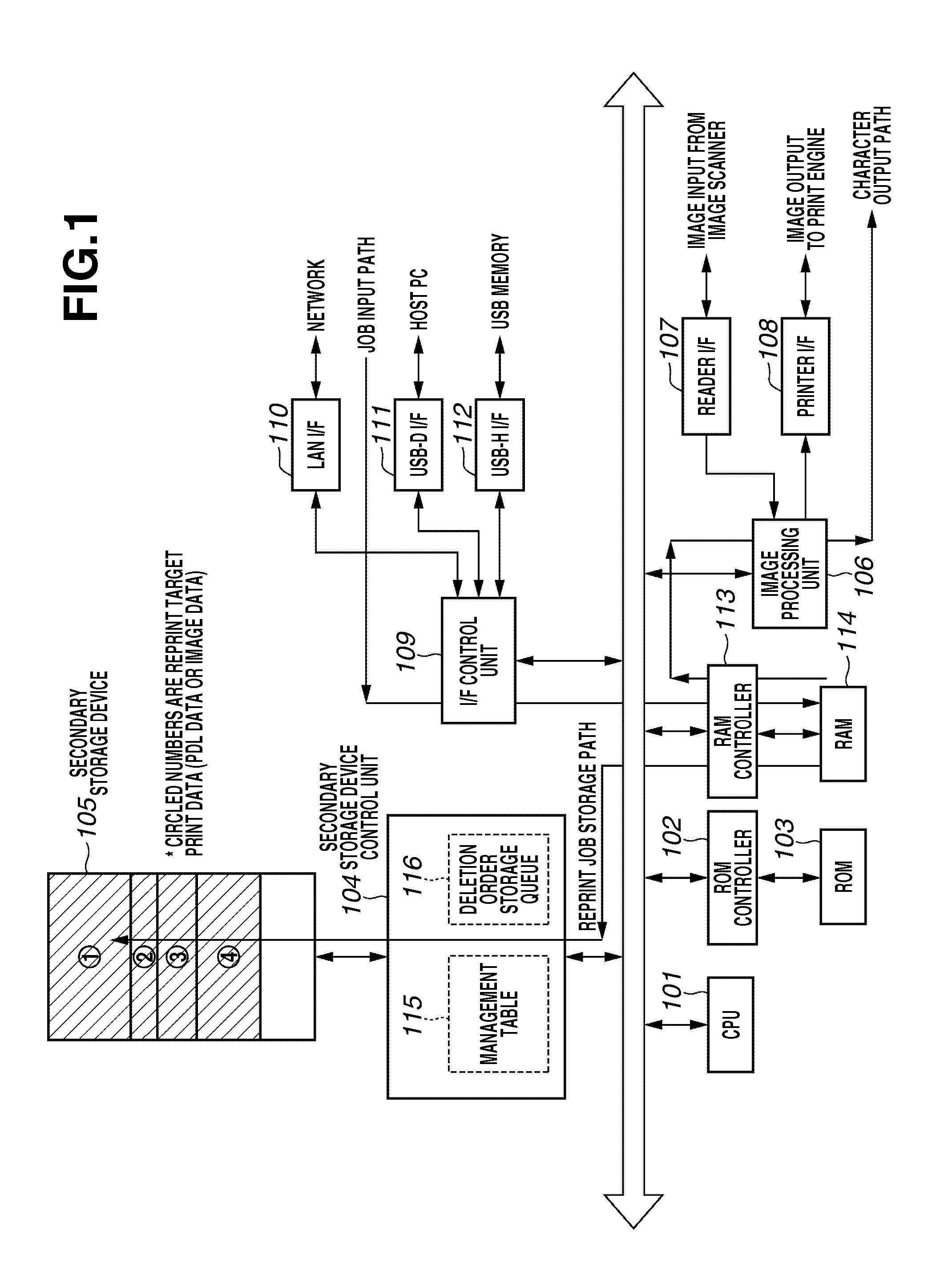
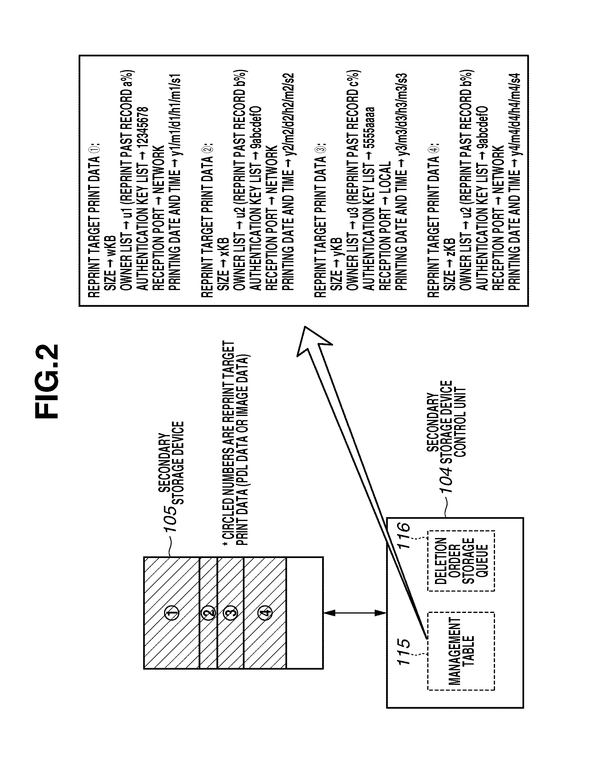
[0019]Various exemplary embodiments, features, and aspects of the invention will be described in detail below with reference to the drawings. One disclosed feature of the embodiments may be described as a process which is usually depicted as a flowchart, a flow diagram, a timing diagram, a structure diagram, or a block diagram. Although a flowchart or a timing diagram may describe the operations or events as a sequential process, the operations may be performed, or the events may occur, in parallel or concurrently. In addition, the order of the operations or events may be re-arranged. A process is terminated when its operations are completed. A process may correspond to a method, a program, a procedure, a method of manufacturing or fabrication, a sequence of operations performed by an apparatus, a machine, or a logic circuit, etc.

[0020]An image forming apparatus according to a first exemplary embodiment is, for example, a common SFP that forms an image after receiving print data inp...


PUM


Abstract

A printing apparatus having a reprint function includes a determination unit to determine whether newly input print data are able to be stored in an empty area of a data storage area, a selection unit to, if the determination unit determines that the newly input print data are not able to be stored in the empty area of the data storage area, select print data that matches a priority deletion condition from among print data pieces that have already been stored, a change unit to change, among deletion order information indicating a deletion order of the print data pieces stored in the data storage area, a deletion order corresponding to the print data selected by the selection unit, a deletion unit to delete corresponding print data based on the deletion order information, and a storage unit configured to store the newly input print data in the empty area.

Description

BACKGROUND OF THE INVENTION[0001]1. Field of the Invention[0002]Embodiments of the present invention relate to a printing apparatus, a data storage method, and a program.[0003]2. Description of the Related Art[0004]Recent single function printers (SFP) tend to use a secure digital (SD) card or a universal serial bus (USB) memory configured from a semiconductor storage element as a secondary storage device instead of a hard disk drive (HDD). Further, attempts are being made to make this storage capacity as small as possible and to reduce costs. On the other hand, as functions in a SFP, separate from the conventionally used BOX storage function, models are appearing that are newly provided with a reprint function. A “BOX storage function” is a function of storing print data for which an output instruction has been issued from a personal computer (PC) in a secondary storage device on the SFP side, and outputting the print data “at any time” based on a SFP operation. In contrast, unlike...

Claims


Application Information

Patent Timeline
IPC IPC(8): G06K15/00
CPCG06K15/1817
Inventor KAWAGUCHI, TADASHI
Owner CANON KK
Learn More