

Valved applicator
- Summary
- Abstract
- Description
- Claims
- Application Information
AI Technical Summary
Benefits of technology
Problems solved by technology
Method used
Image

Examples
second embodiment
[0044]FIG. 7 is an overall illustrative diagram in vertical section of an applicator of the
[0045]FIGS. 8 to 11 are illustrative diagrams of an applicator and its agitator of the third embodiment; FIGS. 12 to 14 are illustrative diagrams of an applicator and its agitator of the fourth embodiment; FIGS. 15 to 18 are illustrative diagrams of an applicator and its agitator of the fifth embodiment; and FIGS. 19 to 20 are illustrative diagrams of an applicator and its agitator of the sixth embodiment.
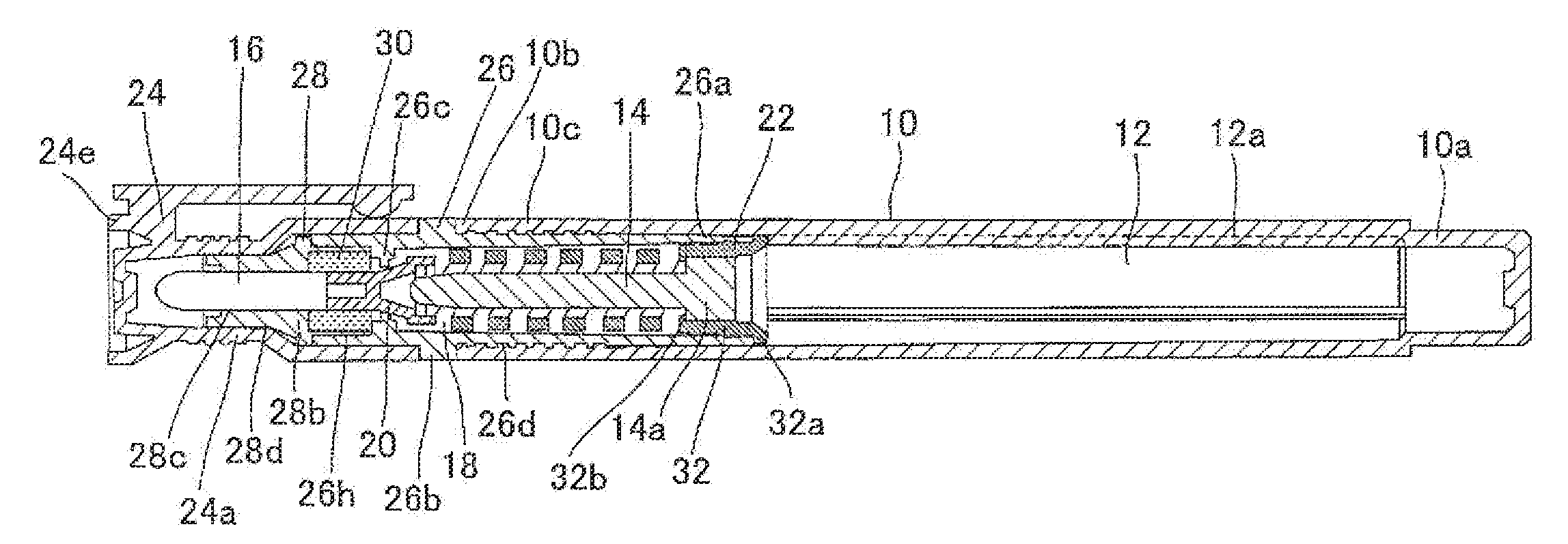
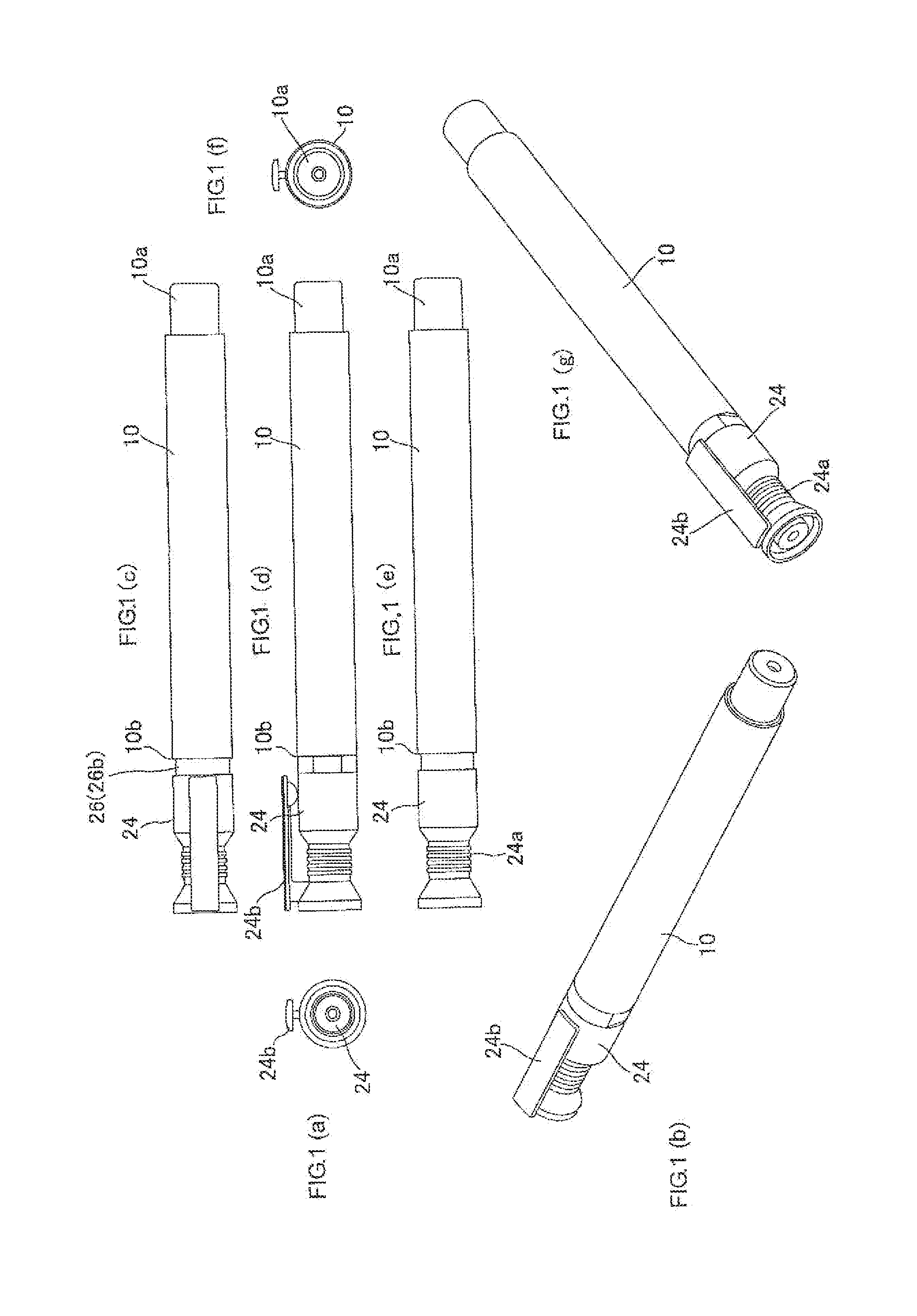
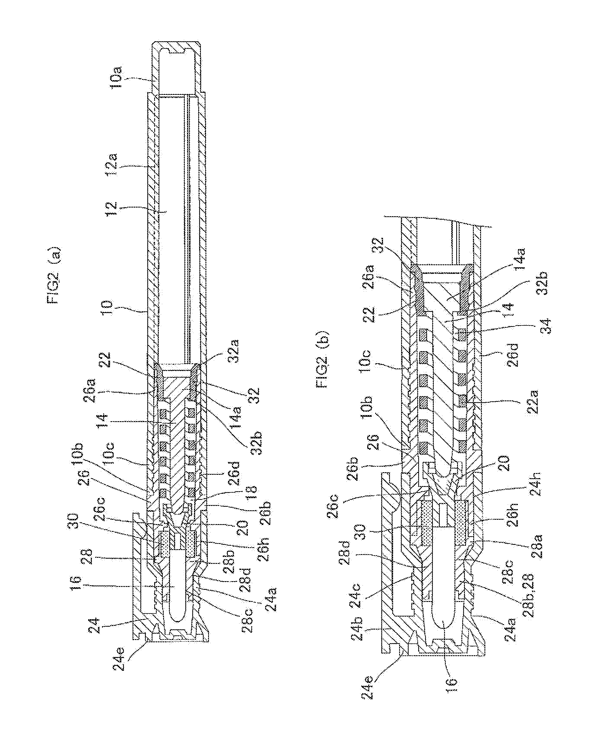
[0046]As shown in FIGS. 1 and 2, a valved applicator is configured such that an ink tank 12 that is located in the rear part of a barrel cylinder 10 for storing ink is communicated with the interior of the front part of barrel cylinder 10, an agitator 14 is arranged inside the ink tank 12 while an applying part 16 with its front end projected out, a valve element 20 that opens and closes an ink flow path 18 and a spring part 22 that elastically urges the valve element 20 forwards are arranged...
first embodiment
[0083]Also, each component of the applicator according to the present invention is preferably formed of resin materials. In the first embodiment, applying part 16 is formed of a bundle of fibers, continuous-foamed body, molding or the like of polyethylene terephthalate (PET). The barrel cylinder 10, front barrel 26, holder 28 and cap 24 are formed of polypropylene (PP). Spring part 22 and agitator 14 are formed of polyacetal (POM) while sponge 30 is formed of urethane. Further, each part is formed by injection molding. Since barrel cylinder 10 and front barrel 26 are formed with high precision by injection molding, the opposing screw-joint parts can be made with high precision while rear end 10a is formed with little burrs so that the external appearance can be improved.
[0084]The operation of the applicator according to the first embodiment will be described.
[0085]During storage of the applicator, the applying part 16 is placed downwards or the like while valve element 20 at the fro...
third embodiment
[0101]FIGS. 8(a) to (b) are overall illustrative diagrams of an applicator ; FIGS. 9(a) to (e) are illustrative diagrams of the applicator, in which a spring part with a valve element integrally formed at the front end thereof is assembled with an applying part and a sponge part and is attached with an agitator; FIGS. 10(a) to (e) are illustrative diagrams of an agitator arranged inside the applicator; and FIG. 11 is a perspective view of an agitator arranged inside the applicator.
[0102]As shown in FIG. 8, the applicator according to the third embodiment has the same configuration as the applicator according to the second embodiment shown in FIG. 7, except in that the configuration of an agitator 14X is significantly different, ribs are formed inside ink tank 12 and clip 24b is provided for cap 24. The same components are allotted with the same reference numerals.
[0103]As shown in FIGS. 8 to 11, agitator 14X provided for the applicator according to the third embodiment is given in a...
PUM
 Abstract
Description
Claims
Application Information