Polyaxial fastener systems and methods

Active Publication Date: 2012-06-07
SMITH & NEPHEW INC
View PDF37 Cites 31 Cited by
  • Summary
  • Abstract
  • Description
  • Claims
  • Application Information

AI Technical Summary

Benefits of technology

[0008]One or both of a structure configured to be implanted in or stabilize a first bone fragment and a fastening assembly can be used to treat bone fractures. The structure may take the form of a plate or other device for at least partial application to the outer surface of bone, or an implant for at least partial implantation within bone. Such implants may include a proximal section having a transverse aperture, and an aperture substantially along their length. Preferably, they include at least one cross-section in their proximal portions which features a shape that imparts additional strength and resistance to tension. Such shapes can be provided, for instance, by (1) adding additional mass in lateral portions of the cross section, and/or (2) strategically adding and reducing mass in the cross section to take advantage of flange effects similar to the w

Problems solved by technology

When an additional screw or pin is used, however, unequal forces applied to the separated screws or pins can cause the separate screws or pins to be pressed against the sides of the holes through which the separate screws or pins are intended to slide.
This may result in binding, which reduces the slid

Method used


Image

  • Polyaxial fastener systems and methods
  • Polyaxial fastener systems and methods
  • Polyaxial fastener systems and methods

Examples


Embodiment Construction

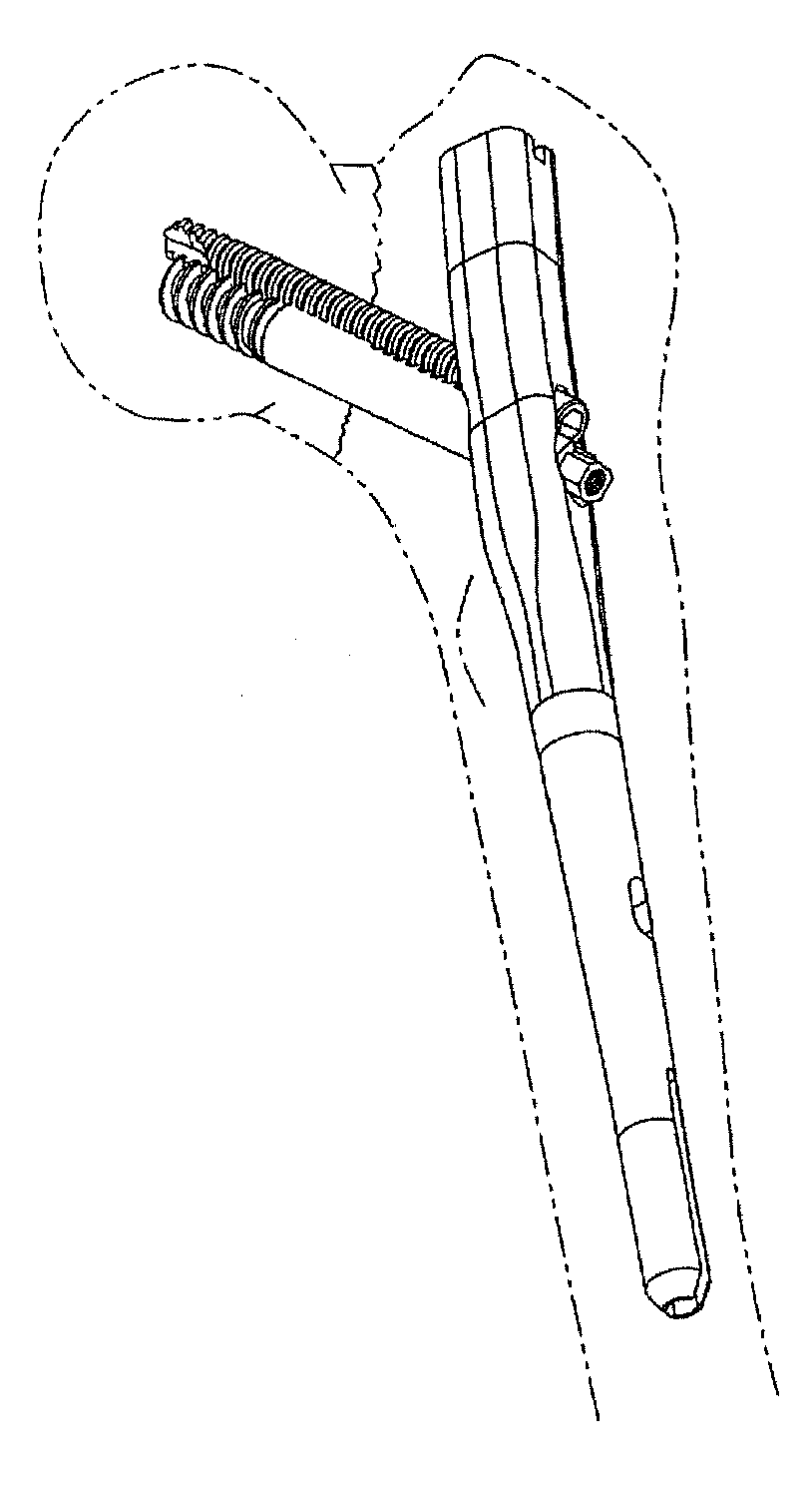
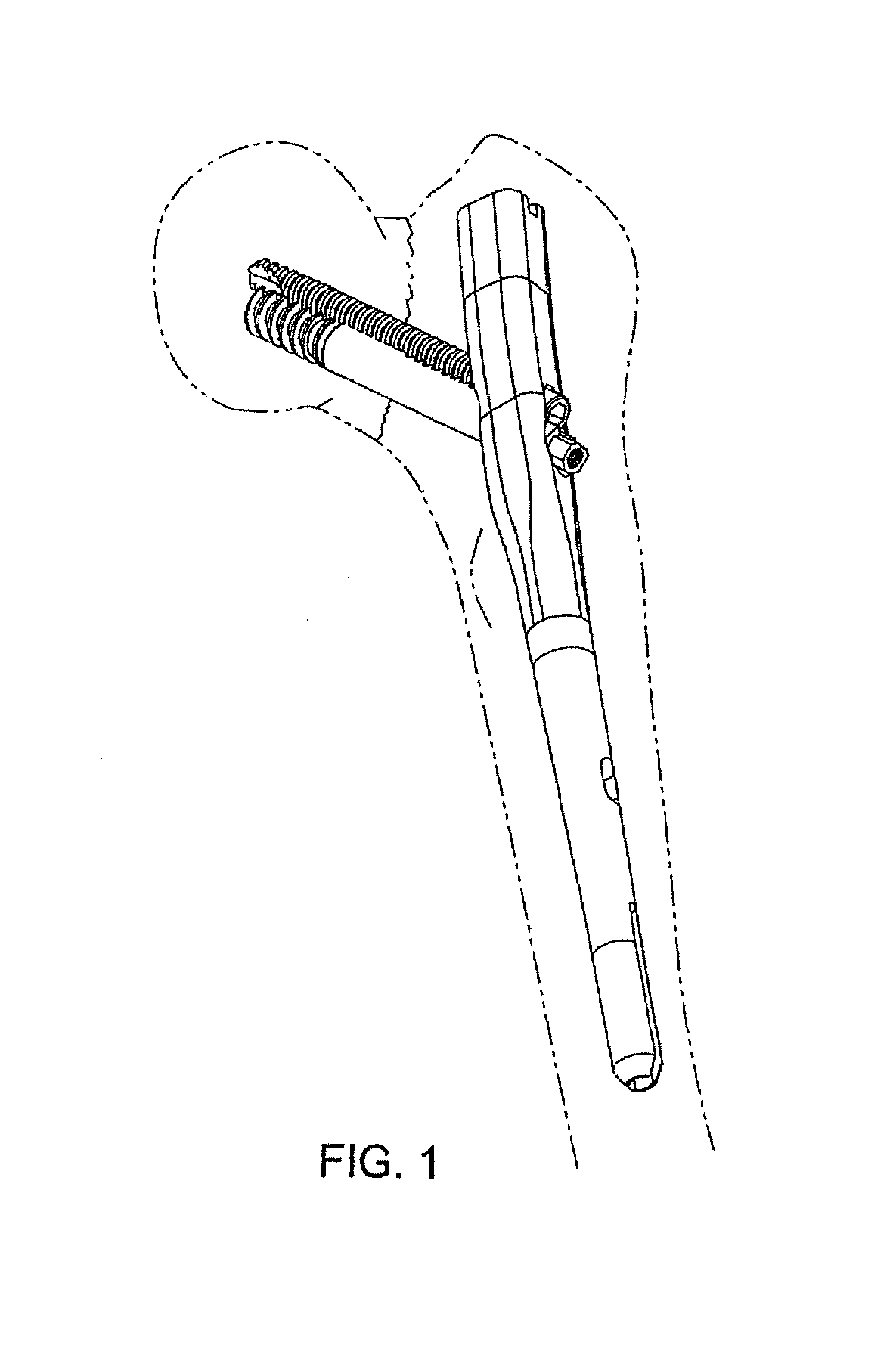
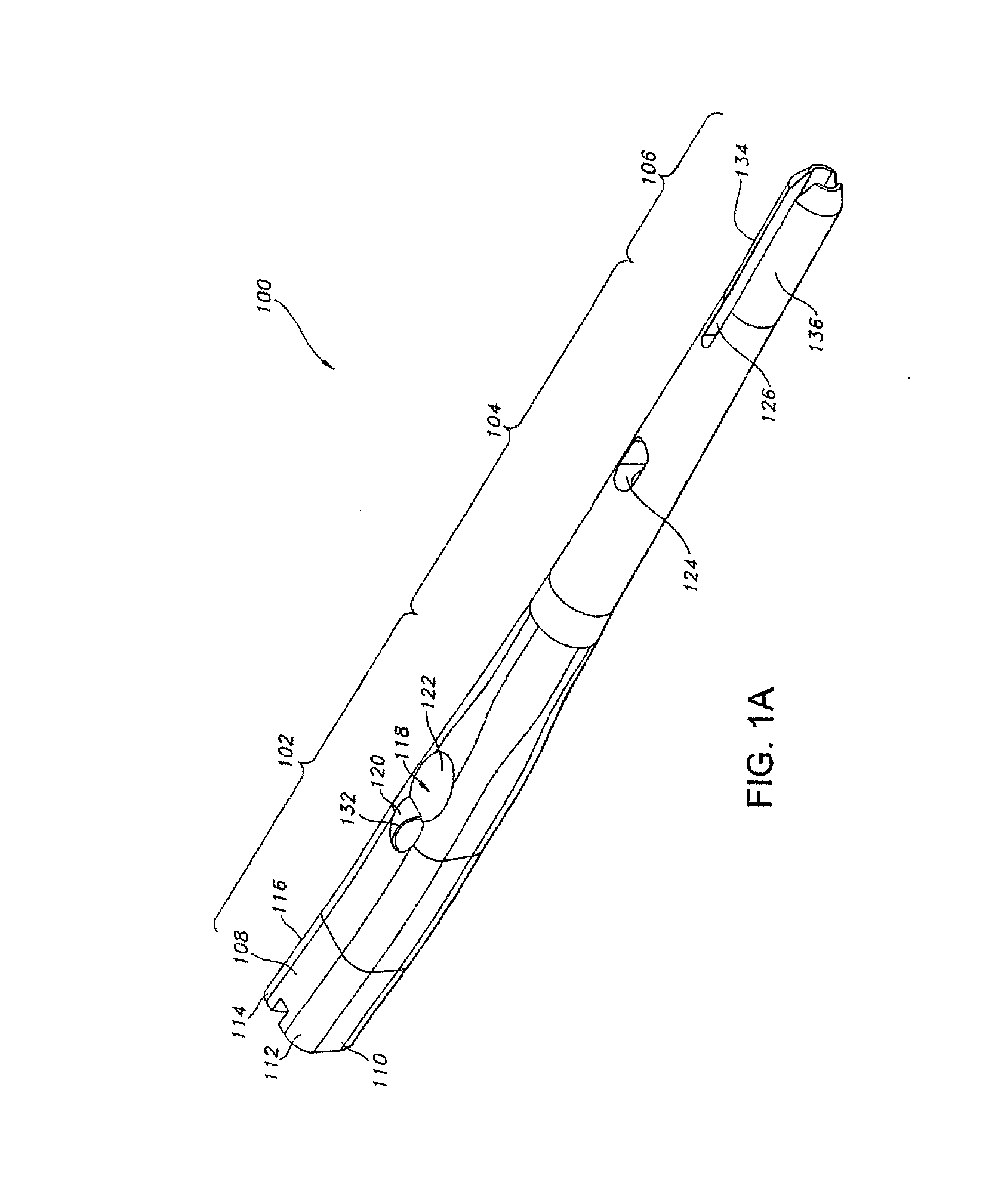
[0079]Methods, devices and systems according to implementations of this disclosure seek to provide improved treatment of femur fractures. FIGS. 1-6 illustrate various views of one implementation of an intramedullary nail 100. The intramedullary nail 100 has a longitudinal bore 130 throughout to aid in insertion in the bone. The intramedullary nail 100 has a proximal section 102, a transition section 104, and a distal section 106.

[0080]The proximal section 102 of the particular structure shown in FIGS. 1-6 preferably features an anatomically inspired shape that corresponds more accurately to typical cortical bone. One version of such shape is shown in the cross-sectional view of the proximal section 102 in FIG. 6. The particular cross-section of the proximal section 102 shown in FIG. 6 is generally non-circular and exists along at least some portions of the length of the intramedullary nail 100. The cross-section of FIG. 6 has a lateral side or aspect 108 that is larger than a medial...


PUM


Abstract

Treating fractures using one or both of an implant, such as an intramedullary nail, and a fastening assembly, such as a lag screw and compression screw assembly. The implant in some implementations has a proximal section with a transverse aperture having a non-circular cross-section that may be shaped to selectively constrain the fastening assembly within the transverse aperture. Two or more components of the fastening assembly may be received to slide, in a controlled way, in the transverse aperture of the implant, and to cooperate to resist a force moment applied thereto.

Description

CROSS REFERENCE TO RELATED APPLICATION[0001]This application claims priority to U.S. Provisional Patent Application Ser. No. 61 / 222,078, filed on Jun. 30, 2009, the entire contents of which are incorporated herein by reference.BACKGROUND[0002]1. Technical Field[0003]This disclosure relates to orthopaedic implants and fastener assemblies.[0004]2. Description of the Related Art[0005]There are a variety of devices used to treat fractures of the femur, humerus, tibia, and other long bones. For example, fractures of the femoral neck, head, and intertrochanteric region have been successfully treated with a variety of compression screw assemblies, which include generally a compression plate having a barrel member, a lag screw and a compressing screw. Examples include the AMBI® and CLASSIC compression hip screw systems offered by Smith & Nephew, Inc. In such systems, the compression plate is secured to the exterior of the femur, and the barrel member is inserted in a predrilled hole in the ...

Claims


Application Information

Patent Timeline
IPC IPC(8): A61B17/72
CPCA61B17/7225A61B17/7233A61B17/725A61B17/8061A61B17/7283A61B17/744A61B17/746A61B17/7266A61F2002/3613Y10S623/911
Inventor WATANABE, KOHSUKESANDERS, ROY W.
Owner SMITH & NEPHEW INC
Why Eureka
Try Eureka