Vacuum pump

a vacuum pump and vacuum technology, applied in the field of vacuum pumps, can solve the problems of serious problems in the operation deterioration of the performance of the turbo-molecular pump, etc., and achieve the effect of reducing the size and cost of the temperature control system

Active Publication Date: 2012-06-07
EDWARDS JAPAN
View PDF17 Cites 10 Cited by
  • Summary
  • Abstract
  • Description
  • Claims
  • Application Information

AI Technical Summary

Benefits of technology

[0063]As explained above, according to the present invention, the number of cooling units or heating units is smaller than the number of temperature sensors, which leads to reduction in size and cost of the temperature control system. Further, even w

Problems solved by technology

When the precipitate of the process gas is deposited in the turbo-molecular pump 100, the deposited substance narrows the flow passage of the pump, which cau

Method used


Image

  • Vacuum pump
  • Vacuum pump
  • Vacuum pump

Examples


first embodiment

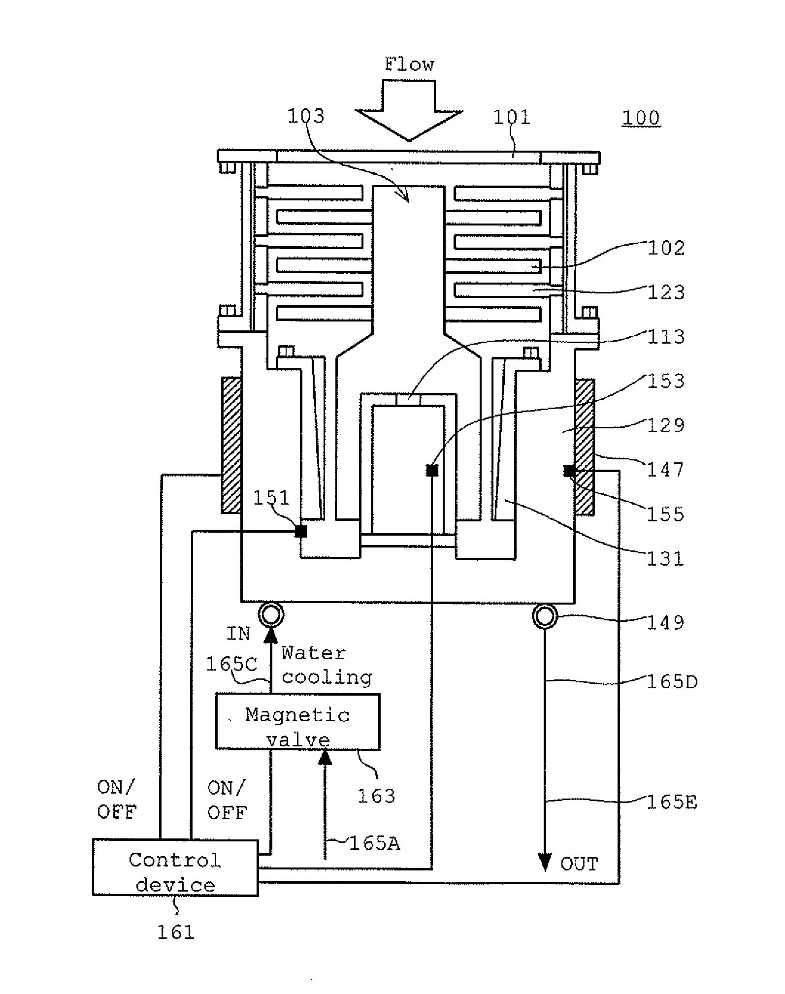
[0073]Next, explanation will be made on a timing chart of temperature control. One temperature sensor is arranged for each target in the pump, while only one set consisting of the heater 147 and the magnetic valve 163 is arranged. In the present first embodiment, one set consisting of a heater and a magnetic valve is controlled based on output signals from a plurality of temperature sensors, based on the priorities set for the temperature sensors.

[0074]FIG. 3 shows an example of a temperature control timing chart when priorities are set for the temperature sensors. In FIG. 3, detection signals of the TMS temperature sensor 151 and the OP sensor 155 are shown on the upper side, and a magnetic valve control command signal and a heater control command signal generated based on these detection signals are shown on the lower side. Set temperatures 201 and 211 are provided for the detection signal of the TMS temperature sensor 151 and the detection signal of the OP sensor 155, respectivel...

second embodiment

[0105]In the present embodiment, similarly to the second embodiment, a higher priority is given to the ON command when controlling the heater 147 and the magnetic valve 163. Specifically, a control command signal serving as an ON command signal is generated based on a logical sum.

[0106]As long as no abnormality is caused in heating, an ON command signal for the heater 147 may be generated similarly to the magnetic valve 163, by using the logical sum of ON commands derived from the detection signals of a plurality of temperature sensors.

[0107]Further, when the temperature exceeds the maximum set temperature value 303, the control command for the magnetic valve 163 based on the motor temperature sensor 153 is continuously applied until the temperature falls below the minimum set temperature value 305. Further, when the temperature becomes the minimum set temperature value 305 or less, the control command for the magnetic valve 163 based on the motor temperature sensor 153 is continuou...


PUM


Abstract

To provide a vacuum pump capable of performing temperature control using one or more heating devices or cooling devices fewer than the number of temperature sensors arranged in the pump.
One temperature sensor is arranged for each target in the pump, while only one set consisting of a heater 147 and a magnetic valve 163 is arranged. One set consisting of a heater and a magnetic valve is controlled based on output signals from a plurality of temperature sensors, based on the priorities set for the temperature sensors. As stated above, by setting priorities for the temperature sensors, the temperature of a target provided with a temperature sensor given a higher priority is settled within a control range by performing quick ON/OFF control, and then the temperature of a target provided with a temperature sensor given a lower priority is settled within the control range.

Description

TECHNICAL FIELD[0001]The present invention relates to a vacuum pump having a heating device or a cooling device, and particularly relates to a vacuum pump capable of performing temperature control using one or more heating devices or cooling devices fewer than the number of temperature sensors arranged in the pump.BACKGROUND ART[0002]As a result of the recent development of electronics, there is a rapid increase in the demand for semiconductor devices such as memories and integrated circuits.[0003]Such a semiconductor device is manufactured by doping impurities into a highly pure semiconductor substrate to impart electrical properties thereto, and forming a minute circuit on the semiconductor substrate by etching, for example.[0004]Such operations must be performed in a chamber in a high-vacuum state to avoid the influence of dust or the like in the air. A vacuum pump is generally used to evacuate the chamber. In particular, a turbo-molecular pump, which is a kind of vacuum pump, is...

Claims


Application Information

Patent Timeline
IPC IPC(8): G05D23/00
CPCF04D29/584F04D19/042F04D27/001F05D2270/303
Inventor MIWATA, TOORUISHII, KEIICHIMACHIDA, KATSUHIDEOHTACHI, YOSHINOBUMAEJIMA, YASUSHITAKAADA, TSUTOMU
Owner EDWARDS JAPAN
Why Eureka
Try Eureka