Arc welding method and arc welding apparatus

a control method and arc welding technology, applied in the direction of arc welding apparatus, welding tools, manufacturing tools, etc., can solve the problems of unstable arc, difficult stable control of welding current and welding voltage, and difficult to match welding voltage with the set voltage, so as to reduce the load on the peripheral components around the motor, such as the feeding motor and gears, and control the welding voltage stably

Active Publication Date: 2012-06-14
PANASONIC CORP
View PDF7 Cites 32 Cited by
  • Summary
  • Abstract
  • Description
  • Claims
  • Application Information

AI Technical Summary

Benefits of technology

[0042]This structure allows the output voltage to be precisely matched with the set voltage, thereby controlling the welding voltage more stably.
[0043]As described above, in accordance with the present invention, in a control method for welding by generating a short-circuit state and an arc state, the short-circuit current increasing gradient, the inflection point at which the short-circuit current increasing gradient changes, the current values in the peak period and in the base period, and the time of the peak period are controlled. This can temporally change the ratio between ...

Problems solved by technology

However, it is considered difficult to match the welding voltage with the set voltage, with the use of a method for outputting the welding current based on the welding voltage, i.e. a typical constant voltage control in the arc pe...

Method used


Image

  • Arc welding method and arc welding apparatus
  • Arc welding method and arc welding apparatus
  • Arc welding method and arc welding apparatus

Examples


first exemplary embodiment

[0055]In this embodiment, a welding control method is described first, and a welding apparatus is described thereafter.

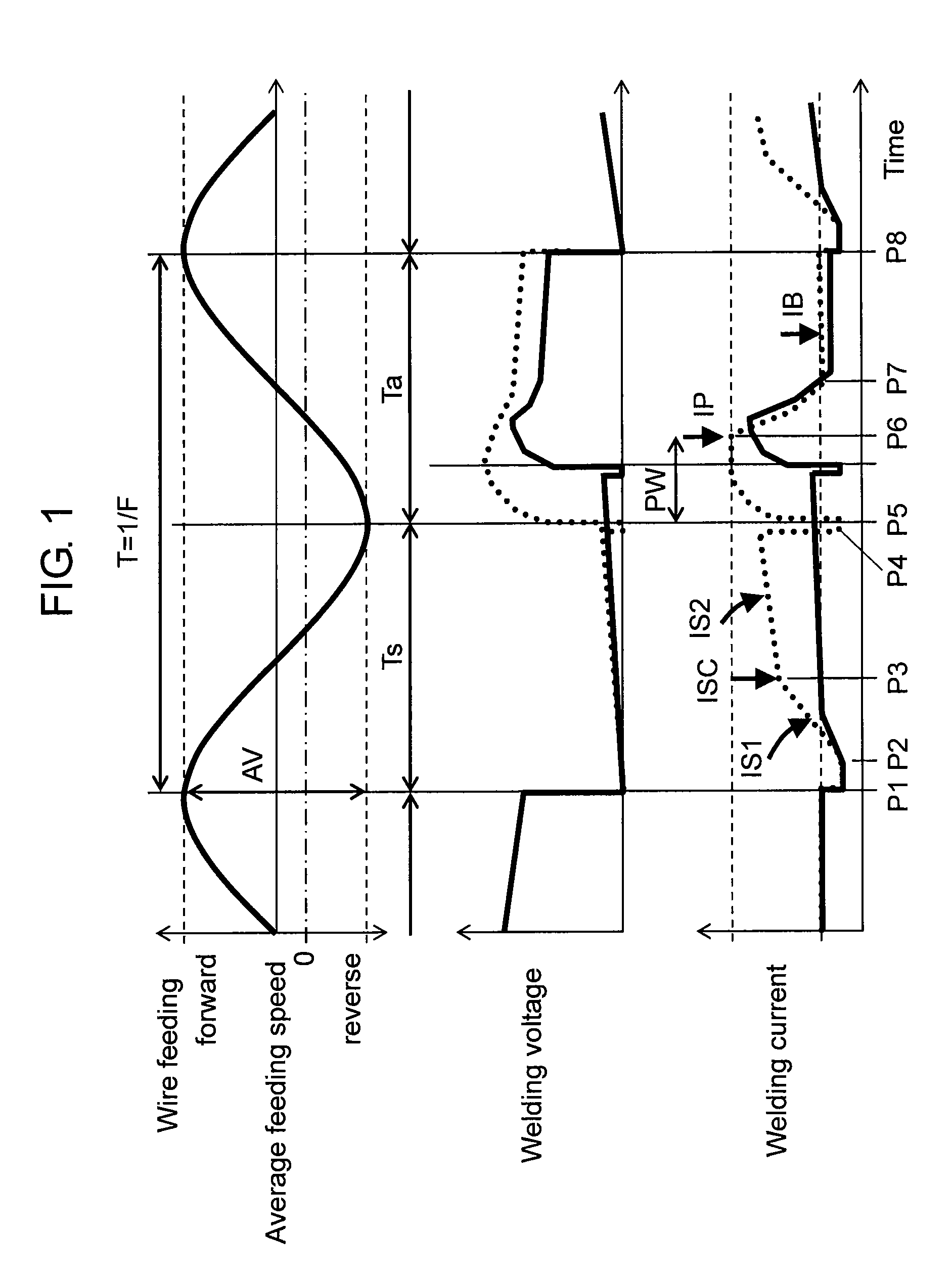
[0056]FIG. 1 and FIG. 2 each shows time waveforms of a wire feeding speed, a welding voltage, and a welding current in a consumable electrode type arc welding for alternately repeating a short-circuit state and an arc state.

[0057]In each of FIG. 1 and FIG. 2, P1 shows a time point at which a short circuit starts, and is also a time point at which a short-circuit initial time starts. P2 shows a time point at which the short-circuit initial time ends. P2 is also a time point at which the output with a short-circuit current increasing gradient (di / dt), i.e. the amount of increase in the short-circuit current per unit time, starts. P3 is a time point of the inflection point of a short-circuit current increasing gradient (di1 / dt) in a first step and a short-circuit current increasing gradient (di2 / dt) in a second step. P4 shows a time point at which the output with the s...

second exemplary embodiment

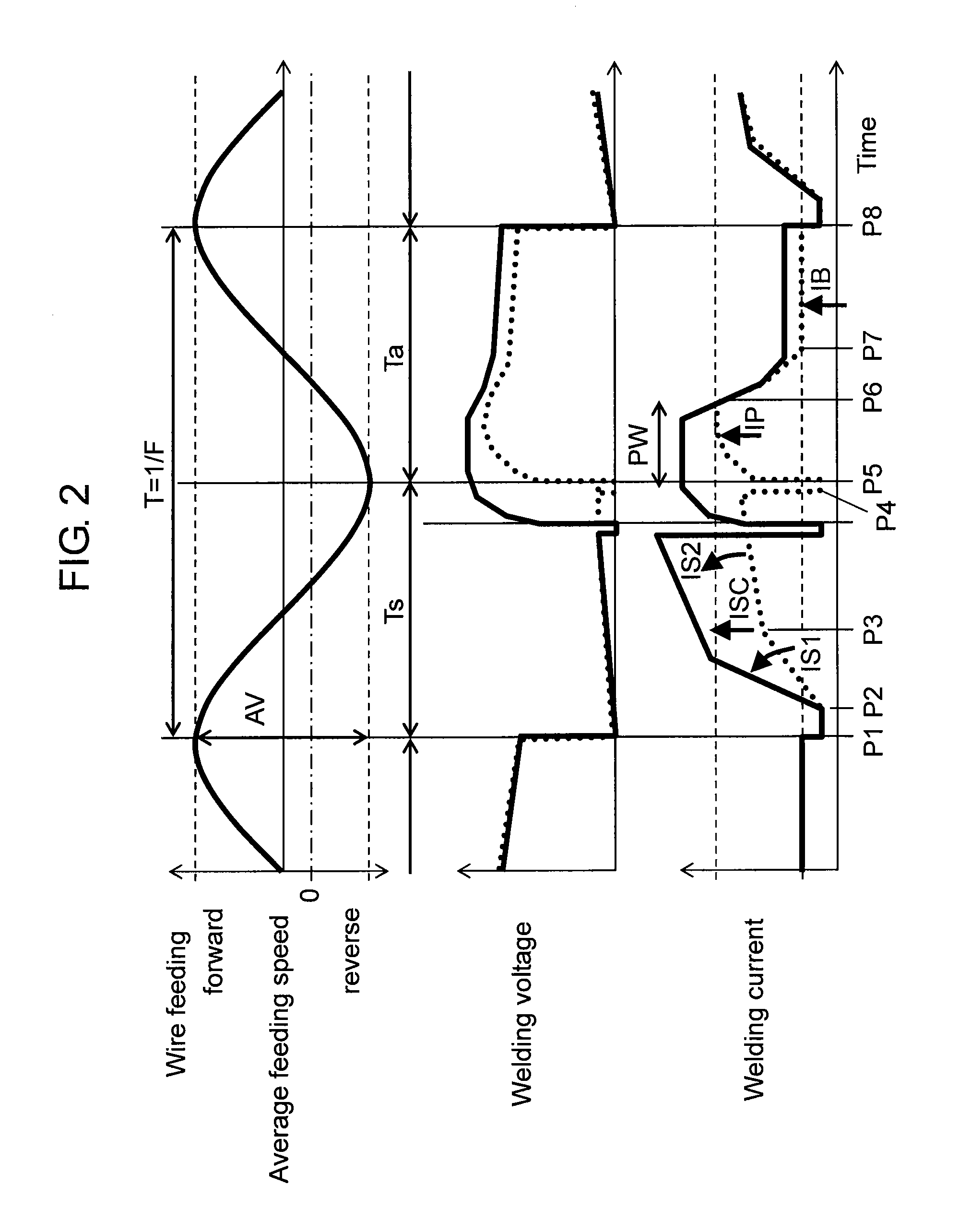
[0174]FIG. 8 is a diagram showing time waveforms of a wire feeding speed, a welding voltage, and a welding current in accordance with the second exemplary embodiment of the present invention. The second exemplary embodiment is different from the first exemplary embodiment mainly in that the wire feeding is based on a trapezoidal waveform as shown in FIG. 8 instead of a sine waveform.

[0175]When wire feeding is controlled such that a forward feed and a reverse feed are periodically repeated at predetermined frequency F with predetermined amplitude AV, such a trapezoidal waveform can provide the performance similar to that of the sine waveform.

[0176]The control method and the welding apparatus are similar to those of the first exemplary embodiment, and thus the description is omitted.

[0177]As described above, in accordance with the present invention, in the control method for periodically increasing or decreasing a wire feeding speed, short-circuit current increasing gradient IS1 in a ...


PUM

PropertyMeasurementUnit
Timeaaaaaaaaaa
Speedaaaaaaaaaa
Currentaaaaaaaaaa

Abstract

An arc welding method of the present invention controls a short-circuit current increasing gradient (di/dt), an inflection point at which the short-circuit current increasing gradient (di/dt) changes, the current in a peak period and in a base period, and the time of the peak period in accordance with a difference between a set voltage and an output voltage. This allows the output voltage to be matched with the set voltage, and stabilizes the arc. Thereby, a stable arc welding method can be implemented, even as a method for outputting a welding current based on a welding voltage.

Description

TECHNICAL FIELD[0001]The present invention relates to an arc welding control method and an arc welding apparatus for welding by alternately generating a short-circuit state and an arc state while repeating a forward feed and a reverse feed of a welding wire as a consumable electrode.BACKGROUND ART[0002]In order to reduce a spatter-removing step, which is a loss step in a welding process, reducing spatters is intended. A conventionally known method for this purpose is a consumable electrode type arc welding method for alternately generating a short-circuit state and an arc state while repeating a forward feed and a reverse feed at a welding wire feeding speed.[0003]FIG. 9 is a diagram showing time waveforms of a wire feeding speed and a welding output with respect to a temporal change in a conventional arc welding control method.[0004]For example, as an arc welding control method for welding by alternately generating a short-circuit state and an arc state while feeding a welding wire...

Claims


Application Information

Patent Timeline
IPC IPC(8): B23K9/10
CPCB23K9/073B23K9/0732B23K9/091B23K9/124B23K9/0956
Inventor FUJIWARA, JUNJIMUKAI, YASUSHIKAWAMOTO, ATSUHIROKOWA, MASARU
Owner PANASONIC CORP
Why Eureka
Try Eureka