Device and method for automatic multiple-bead welding

a technology of multiple beads and welding methods, applied in the field of automatic welding, can solve the problems of difficult triangulation in order to find the edges of weld joints, and achieve the effect of robust joint tracking

Inactive Publication Date: 2012-06-14
ESAB AB
View PDF15 Cites 12 Cited by
  • Summary
  • Abstract
  • Description
  • Claims
  • Application Information

AI Technical Summary

Benefits of technology

[0006]An object of the present invention is to provide a method and a device that enable a robust joint tracking.

Problems solved by technology

However, it is difficult to use triangulation in order to find the edges of a weld joint when the joint is almost filled with weld beads.

Method used


Image

  • Device and method for automatic multiple-bead welding
  • Device and method for automatic multiple-bead welding
  • Device and method for automatic multiple-bead welding

Examples


Embodiment Construction

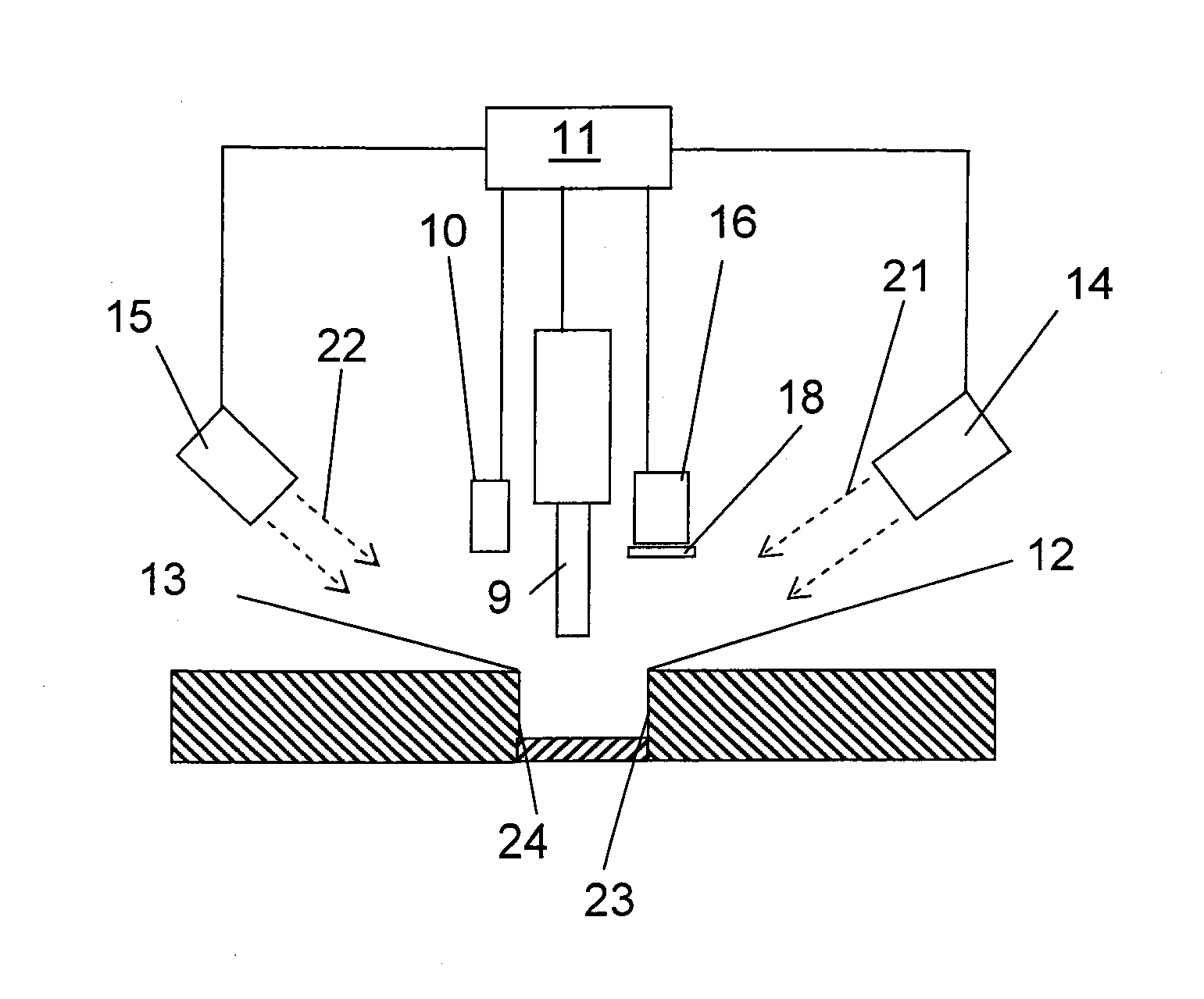
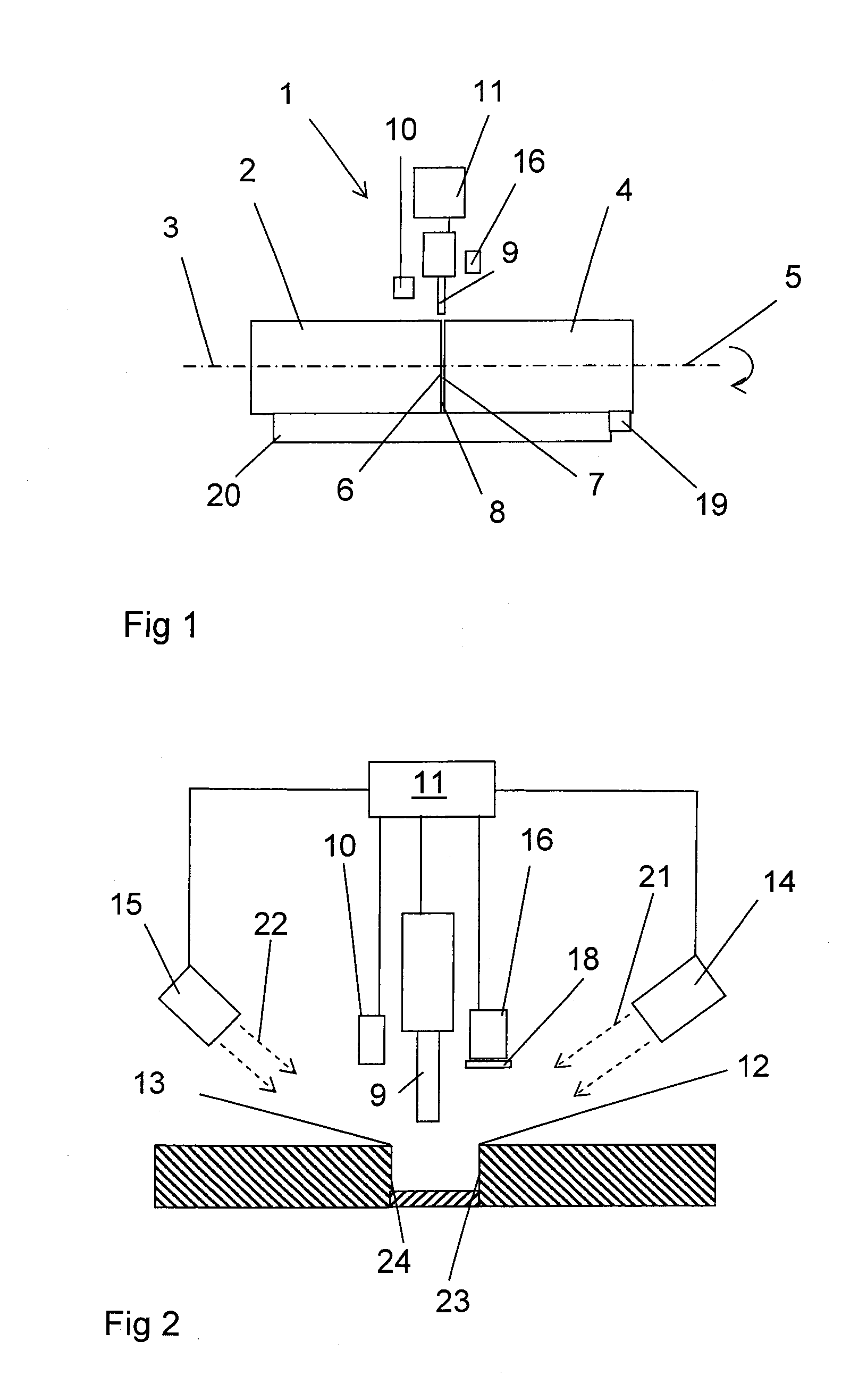
[0029]FIG. 1 shows schematically a welding device 1 for automatic multiple-bead welding of a joint formed by two joint surfaces 23, 24. FIG. 1 shows a first tube 2 with a symmetry axis 3, and a second tube 4 with a symmetry axis 5, wherein the first tube 2 has substantially the same diameter as the second tube 4. The tubes are arranged in a cradle 20, with the first end 6 of the first tube 2 next to the first end 7 of the second tube 4, and with the symmetry axes arranged such that they substantially coincide with each other. The junction between the tubes 2, 4 defines a joint line 8. The tubes 2, 3 can be rotated around their symmetry axes in the cradle 20. The welding device 1 comprises a welding head 9 for the application of weld beads in the joint in order to weld the tubes together, and a line illumination member 10 which is arranged to illuminate the joint by scanning a light beam across the joint line 8. According to an embodiment of the invention, the line illumination membe...


PUM

PropertyMeasurementUnit
angleaaaaaaaaaa
displacementaaaaaaaaaa
transmissionaaaaaaaaaa

Abstract

A welding device and a method for automatic multiple-bead welding, wherein a line illumination member is arranged to illuminate the joint by scanning a light beam across the joint line. A camera is arranged for the registration of line images of the joint when it is illuminated with the scanned light beam. The locations of the edges of the joint are determined by means of triangulation based on the registered line image. The welding device can include a stereo image member arranged to register photometric stereo images of the joint substantially simultaneously with the registration of the line images. The welding device is arranged to, during welding of a weld joint with a plurality of weld beads, control the welding head in dependence on both stereo images and line images.

Description

TECHNICAL FIELD[0001]The present invention concerns automatic welding. More specifically, the present invention concerns a method and a device for automatic multiple-bead welding. The automatic multiple-bead welding comprises joint tracking.BACKGROUND[0002]When welding sheets, the sheets are joined by applying melted metal in the joint between the sheets. The melted metal is called weld bead and may originate from the sheets or from material that has been supplied from a welding wire. For a plurality of products it is necessary to use thick sheets. Examples of such products are ships, pipelines and towers for wind power plants. When welding thick sheets it is not possible to obtain a strong weld by only welding one single weld bead. In order to obtain a strong weld joint several weld beads are required which are applied in the joint between the sheets. In order for the weld joint to be strong it is required that the successive weld beads are applied upon each other so that they fill...

Claims


Application Information

Patent Timeline
Patent Type & Authority Applications(United States)
IPC IPC(8): B23K31/02B23K37/00
CPCB23K9/1274B23K9/0956B23K9/127
Inventor BOHLIN, GUNNAR
Owner ESAB AB
Why Eureka
Try Eureka