Roof assembly

Inactive Publication Date: 2012-06-14
EMU INNOVATIONS
View PDF3 Cites 3 Cited by
  • Summary
  • Abstract
  • Description
  • Claims
  • Application Information

AI Technical Summary

Benefits of technology

[0010]Embodiments of the present invention provide the significant advantage that the roof assembly may expand so as to cover a region that extends around a corner of the structure in substantially one action. For example, the roof assembly may be arranged such that, as the first and second side portions of the roof assembly move from the retracted to the expanded configuration, the corner roof assembly portion expands substantially simultaneously to cover a region external the structure and extending from a corner of the structure. In one example the structure has a substantially rectangular floor plan and the first and second side roof assembly portions extend from sides that are substantially perpendicular one another so as to cover first and second regions extending from the first and second sides respectively at substantially the same time as the corner roof portion expands to cover a region between the first and second regions.
[0015]The upper portion may be moveable between a lowered configuration and a raised configuration so as to allow the expandable structure to be expandable in a substantially vertical direction. The roof assembly is moveable between a contracted and an expanded configuration so as to provide an expandable roof. The upper portion may provide cover for the expandable structure and the roof assembly may provide shelter for a region external the expandable structure when the roof assembly is in the expanded configuration. The upper portion may be arranged so as to house the roof assembly when in the contracted configuration and to which the roof assembly is attached when expanded.
[0016]Embodiments of the second aspect of the present invention provide the significant advantage of allowing the expandable structure to be relatively compact when the roof portion is lowered and the roof assembly is retracted so as to allow for convenient transport and / or storage.
[0027]The roof assembly may further comprise additional roof portions and / or wall portions that are arranged for coupling to the roof assembly when in the expanded configuration. For example, the roof assembly may form a base to which the additional roof portions may be coupled so as to extend an amount of coverage provided. The structure may be coupled to the additional roof portions, or the roof assembly, so as to provide a wall portion that is spaced from the wall portions of the structure. This provides the significant advantage of providing a shelter that may be set up quickly and conveniently. After the roof assembly has been moved into the expanded configuration, typically in one action, the additional roof portions and / or wall portions may be added to expand the shelter. The initial expansion of the roof assembly may provide shelter while the additional roof portions and / or wall portions are being added.

Problems solved by technology

The shelter would then be set up manually which requires a substantial amount of effort, time and manpower.
Such shelters, and in particular the containers they are transported in, are not compact and / or convenient to transport.
The containers take up valuable room when in storage or in the process of transportation.
Further, if the material for providing the shelter has been airlifted to a location, for example in a region where the terrain makes it difficult for a truck to transport the container, then subsequently moving the shelter to a new location will require a further airlift which is expensive and presents logistical difficulties.
However, such shelter is often relatively basic.
Such tents leave a lot to be desired in the way of living conditions.
Further, these tents present disadvantages regarding the effort, time and manpower required to set them up.

Method used


Image

  • Roof assembly
  • Roof assembly
  • Roof assembly

Examples


Embodiment Construction

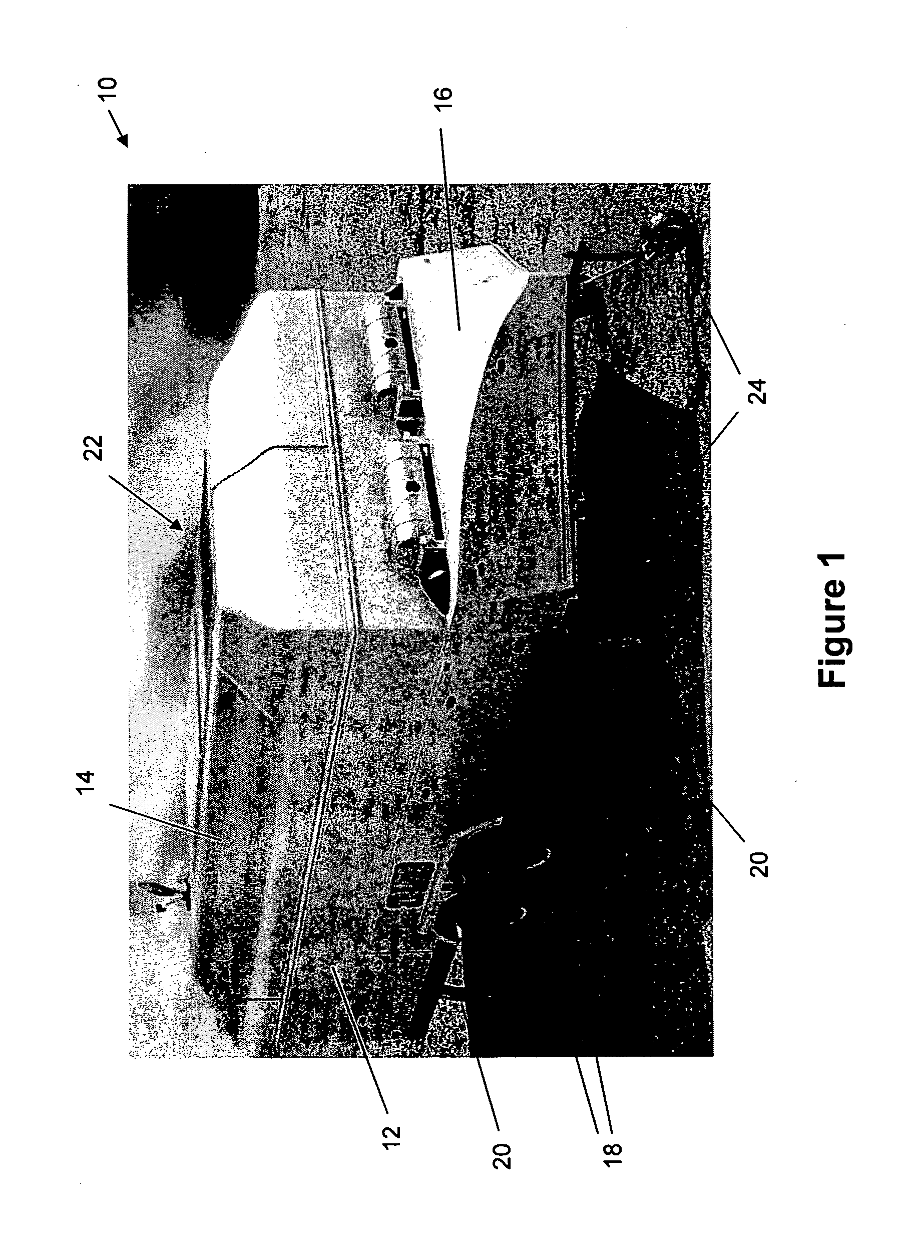
[0070]Specific embodiments of the present invention are now described with reference to FIGS. 1-8 in relation to a roof assembly for covering a region adjacent a structure.

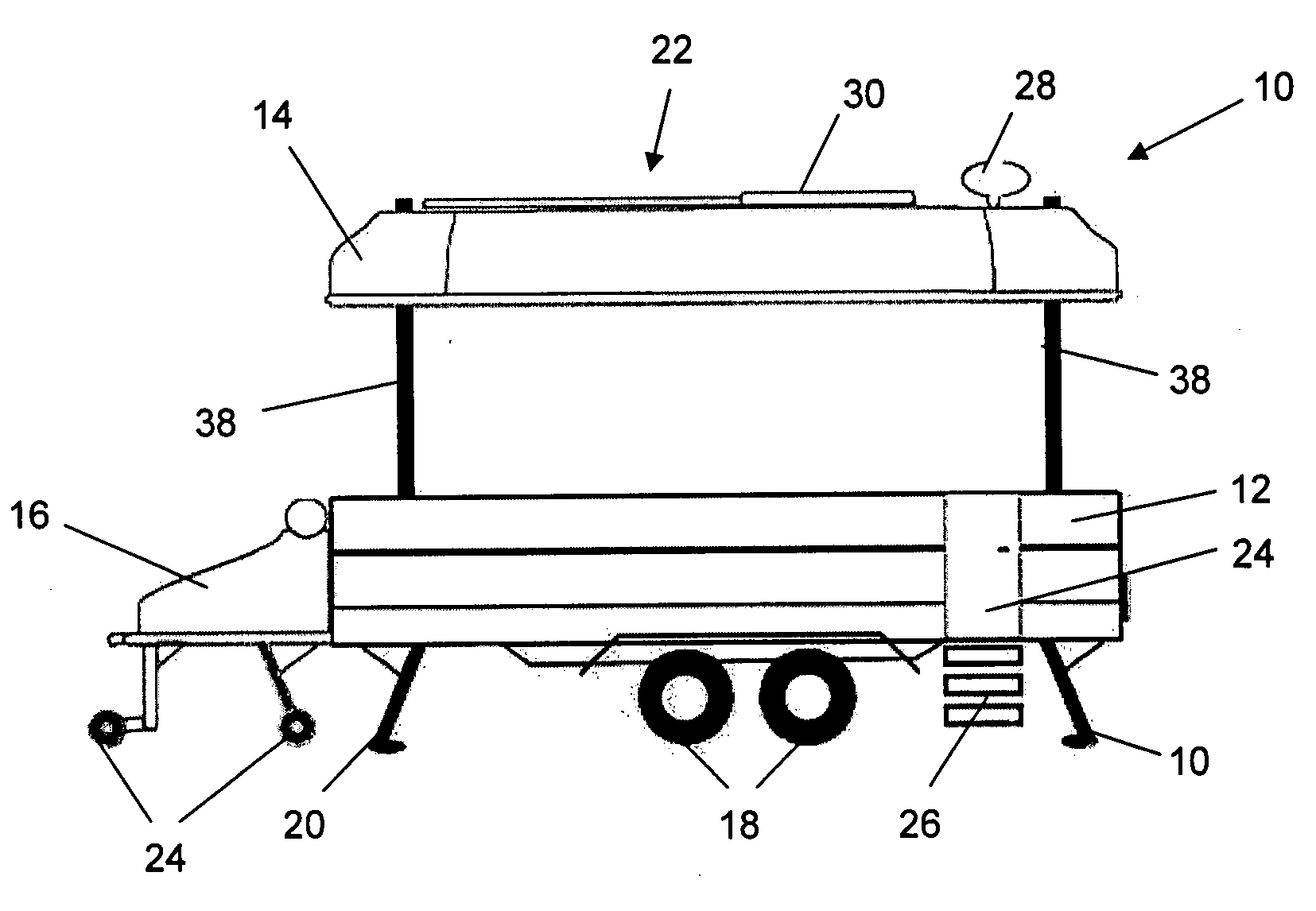
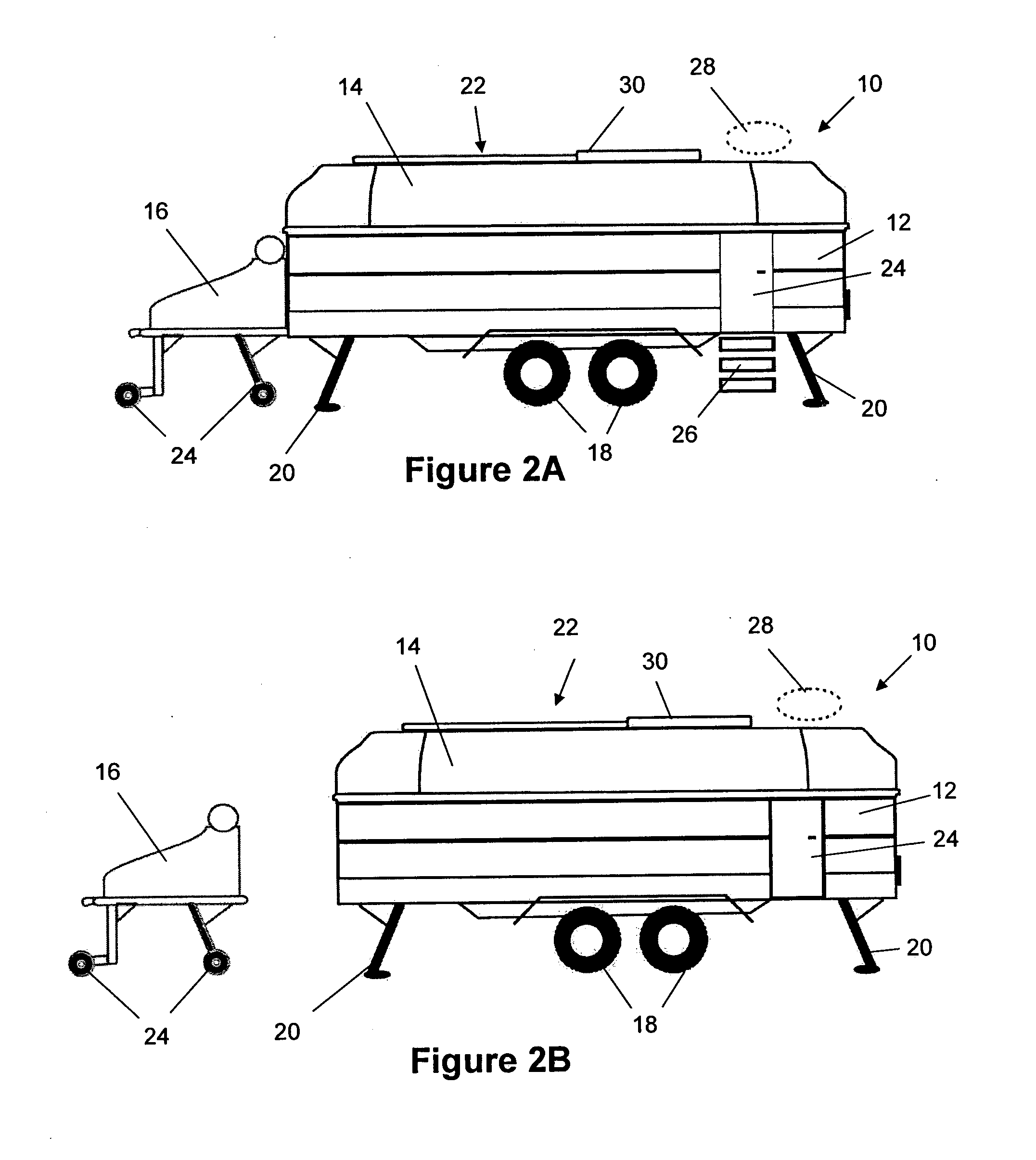
[0071]Referring initially to FIG. 1, there is shown a trailer 10 comprising a base portion 12, an upper portion 14 and a detachable generator 16. The base portion 12 comprises wheels 18 to enable convenient transport of the trailer 10 and retractable support members 20 for stabilizing the trailer 10 in position. The upper portion 14 houses a roof assembly, which is shown and described later, and provides an upper surface 22 for mounting or installing peripherals such as satellite dishes, solar panels, ventilation systems and other attachments and systems. The generator 16 is detachable from the base portion 12 and comprises retractable wheels 24. The retractable wheels 24 may be retracted when the trailer 10 is being transported, for example by attachment to a land vehicle, or may be in a lowered configuration as ...


PUM


Abstract

The present disclosure provides a roof assembly for covering a region adjacent a structure. The roof assembly comprises a plurality of roof assembly portions, each roof assembly portion comprising a layer portion and a support portion for supporting the layer portion. The roof assembly portions comprise first and second side roof assembly portions, and a corner roof assembly portion that is positioned between the first and second side roof assembly portions. The roof assembly portions are moveable between a retracted and an expanded configuration wherein the side roof assembly portions and the corner roof assembly portion move together between the configurations.

Description

FIELD OF THE INVENTION[0001]The present invention broadly relates to a roof assembly.BACKGROUND OF THE INVENTION[0002]Providing shelter in a location where, for example, a first aid centre is needed has previously required that the equipment used to form the shelter be transported to the location in a container such as a shipping container. This may involve transporting the container on a truck or by airlifting the container to the location. The shelter would then be set up manually which requires a substantial amount of effort, time and manpower.[0003]If the shelter needs to be moved again, for example if the shelter is regularly moved from location to location during a safari, emergency response or similar, the shelter will need to be dismantled, re-packed, and then transported to the next location where the shelter is set up again in the same effort and time consuming manner.[0004]Such shelters, and in particular the containers they are transported in, are not compact and / or conv...

Claims


Application Information

Patent Timeline
IPC IPC(8): B60J10/12E04B7/16B60J10/82
CPCB60P3/341E04F10/04B60P3/36
Inventor FIANDER, SUSANNEKEBBELL, NICHOLAS
Owner EMU INNOVATIONS
Why Eureka
Try Eureka