Method of evaluating a clamping portion of an electric wire and a terminal, and device for evaluating the clamping portion

a technology of clamping portion and evaluation device, which is applied in the direction of testing/measuring connectors, line/current collector details, instruments, etc., can solve the problems of mechanical connection performance and electric connection performance differences, and achieve easy evaluation, good clamping portion quality, and easy measurement of terminal length

Active Publication Date: 2012-06-14
YAZAKI CORP
View PDF6 Cites 1 Cited by
  • Summary
  • Abstract
  • Description
  • Claims
  • Application Information

AI Technical Summary

Benefits of technology

[0012]According to the first aspect of the present invention, with the use of a correlation between a crimp height and the expansion of the terminal due to clamping, the lower limit and the upper limit of the expansion of the terminal are set instead of the lower limit and the upper limit of the crimp height. It is determined whether the quality of the clamping portion is good, or not, according to whether the expansion of the terminal measured after clamping falls within the allowable range between the lower limit and the upper limit, or not, and therefore the clamping portion can be easily evaluated. That is, because measuring the length of the terminal is easier than measuring the crimp height, automation can be easily realized whereby all of the clamping portions can be tested. As a result, all performances of the clamping products can be ensured.
[0013]According to the second aspect of the present invention, the terminal is set up on the stand, and it is detected where a tip of the terminal is positioned whereby the quality of the clamping portion can be easily evaluated.
[0014]According to the third aspect of the present invention, the expansion of the terminal is detected by the detection unit, and how long is the expansion is determined by the determination unit whereby the quality of the clamping portion can be easily evaluated.

Problems solved by technology

There has been known that the above connection is liable to cause a difference in electric connection performance and mechanical connection performance due to the clamping quality of the conductor Wa and the wire barrel 11.

Method used


Image

  • Method of evaluating a clamping portion of an electric wire and a terminal, and device for evaluating the clamping portion
  • Method of evaluating a clamping portion of an electric wire and a terminal, and device for evaluating the clamping portion
  • Method of evaluating a clamping portion of an electric wire and a terminal, and device for evaluating the clamping portion

Examples


Embodiment Construction

[0021]Hereinafter, embodiments of the present invention will be described with reference to the drawings.

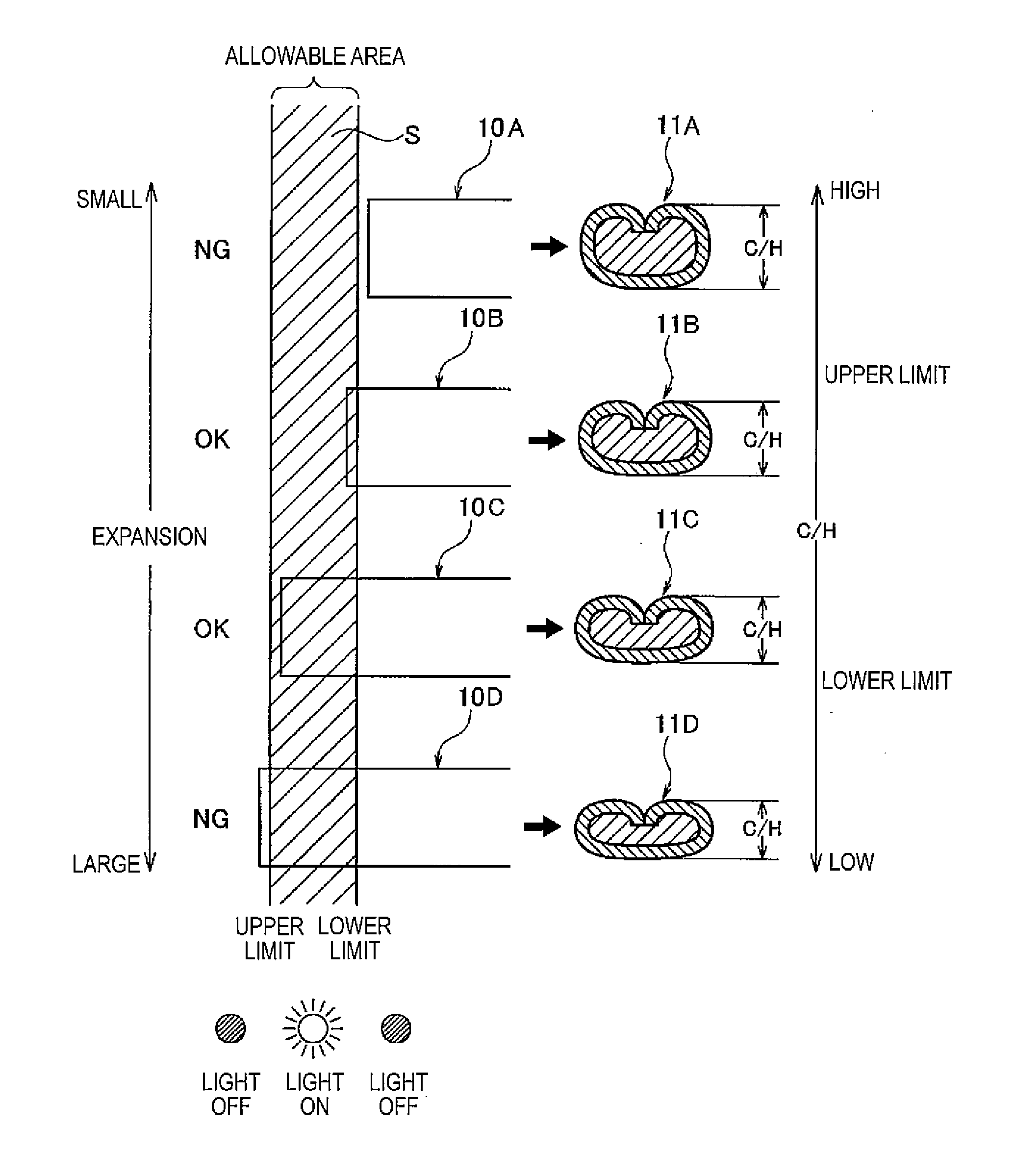
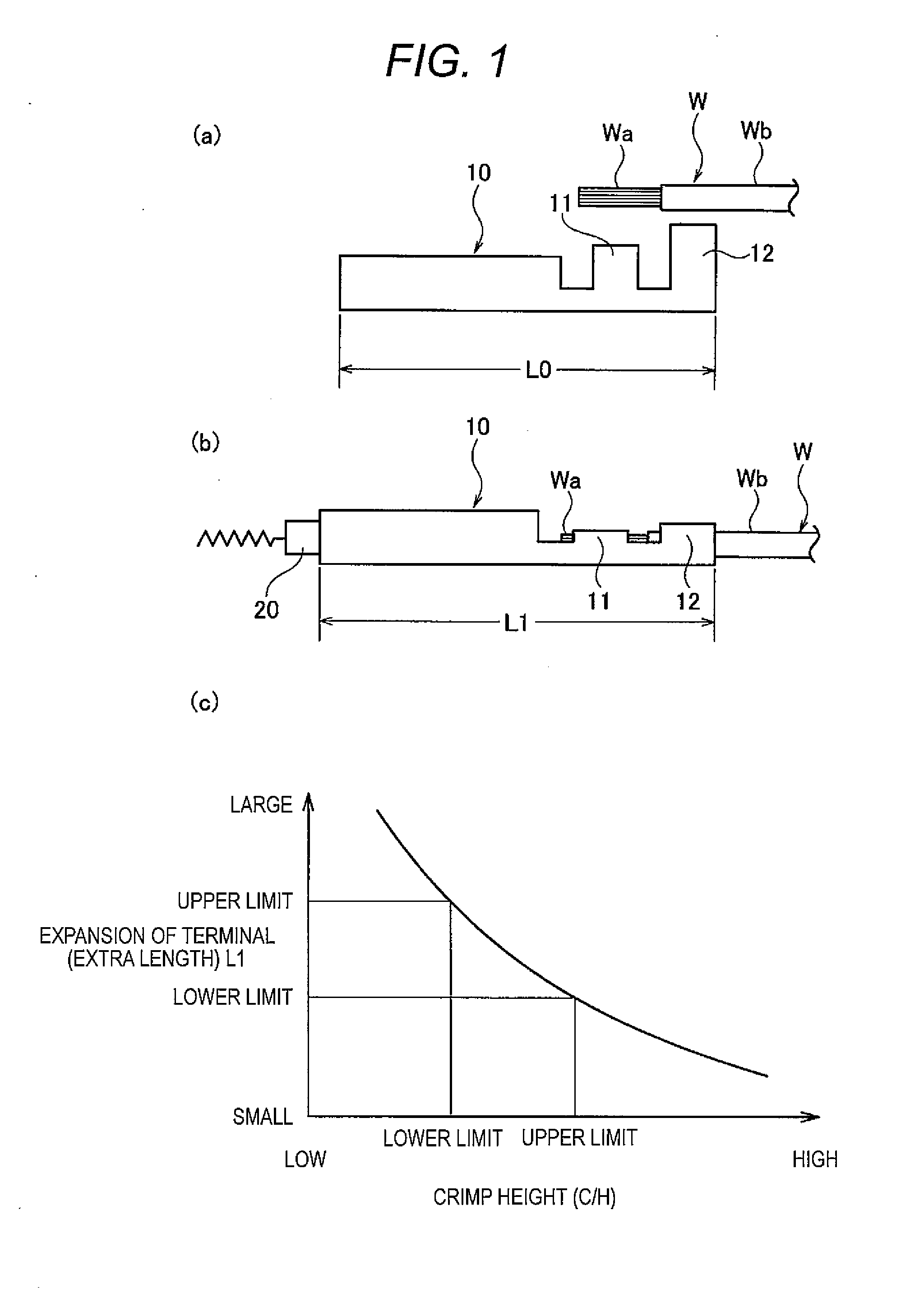
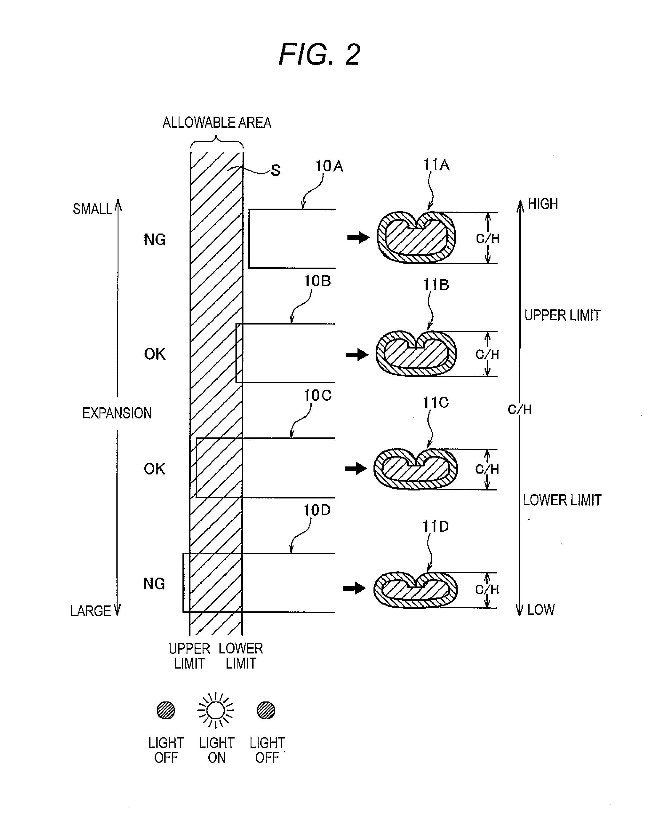
[0022]FIG. 1 is an illustrative diagram of an evaluation method according to an embodiment of the present invention, in which FIG. 1(a) is a side view illustrating a state before a terminal and an electric wire are crimped onto each other, FIG. 1(b) is a side view illustrating a state after the terminal and the electric wire are crimped onto each other, and FIG. 1(c) is a characteristic diagram illustrating a relationship between a crimp height and the expansion of the terminal due to clamping. The configuration of a terminal 10 and the configuration of an electric wire W are identical with those in FIG. 4, and therefore, their description will be omitted.

[0023]In this embodiment, as illustrated in FIGS. 1(a) and 1(b), an overall length L0 of the terminal 10 before clamping are grasped in advance, and an overall length L1 of the terminal 10 after clamping is measured by a detecti...


PUM


Abstract

There is provided a method of evaluating a clamping portion of an electric wire and a terminal, which can determine whether a clamping quality is good, or not, through simple test, and can easily test all of the clamping portions. The method of evaluating the clamping portion of an electric wire (W) and a terminal (10) includes measuring a length (L1) of the terminal (10) after clamping to detect an expansion of the terminal (10) after clamping to a length (L0) of the terminal (10) before clamping, determining that the clamping quality is “good” when the expansion falls within an allowable range between a given lower limit and a given upper limit, and determining that the clamping quality is “no good” when the expansion falls outside the allowable range.

Description

TECHNICAL FIELD [0001]The present invention relates to an evaluation method and an evaluation device for a clamping portion of an electric wire and a terminal.BACKGROUND ART [0002]FIG. 4 illustrates a general configuration example of a clamping terminal. As illustrated in FIG. 4(a), a wire barrel (that is, swaging portion) 11 and an insulation barrel (that is, coated swaging portion) 12, which are U-shaped in cross section are disposed on a rear portion of a terminal 10. When the terminal 10 is connected to an electric wire W, a conductor Wa exposed by stripping an insulating coating Wb of a terminal portion of the electric wire W is inserted into the wire barrel 11, and a portion adjacent to the conductor Wa and formed with the insulating coating Wb is inserted into the insulation barrel 12. Then, in that state, as illustrated in FIG. 5, the wire barrel 11 is rounded inwardly and swaged by a crimper 101 and an anvil 102 of a terminal clamping device whereby the wire barrel 11 of th...

Claims


Application Information

Patent Timeline
Patent Type & Authority Applications(United States)
IPC IPC(8): G01R31/02
CPCH01R2201/20H01R43/048
Inventor ONUMA, MASANORI
Owner YAZAKI CORP
Why Eureka
Try Eureka