Heat exchanger, heat dissipation method of the same and communication apparatus

a heat dissipation method and heat exchanger technology, applied in the field of heat dissipation techniques, can solve the problems of increasing the heat consumption in the unit space, the level of the communication apparatus, and the difficulty of the plate-type heat exchanger core and achieve the effect of small flow resistance and the ability to meet the heat dissipation requirement of the communication apparatus

Inactive Publication Date: 2012-06-14
HUAWEI TECH CO LTD
View PDF21 Cites 6 Cited by
  • Summary
  • Abstract
  • Description
  • Claims
  • Application Information

AI Technical Summary

Benefits of technology

[0012]From the above content, it can be seen that the first group of dissipation tubules are filled with the liquid vaporized when being heated and the liquid vaporized when being heated flows in the first group of dissipation tubules and the second group of dissipation tubules, thus there is a small flow resistance for the air inside and outside the communication apparatus to pass the heat dissipation tubules. So with the increase of the power of the communication apparatus, the heat dissipation requirement of the communication apparatus can be well satisfied.

Problems solved by technology

With the development of the communication technique, the integration level of the communication apparatus is increasingly higher, and the heat consumption in the unit space is continuously increased.
As a result, with the increased power of the communication apparatus, it is difficult for the plate-type heat exchanger core to meet the heat dissipation requirement of the communication apparatus.

Method used


Image

  • Heat exchanger, heat dissipation method of the same and communication apparatus
  • Heat exchanger, heat dissipation method of the same and communication apparatus
  • Heat exchanger, heat dissipation method of the same and communication apparatus

Examples


embodiment 1

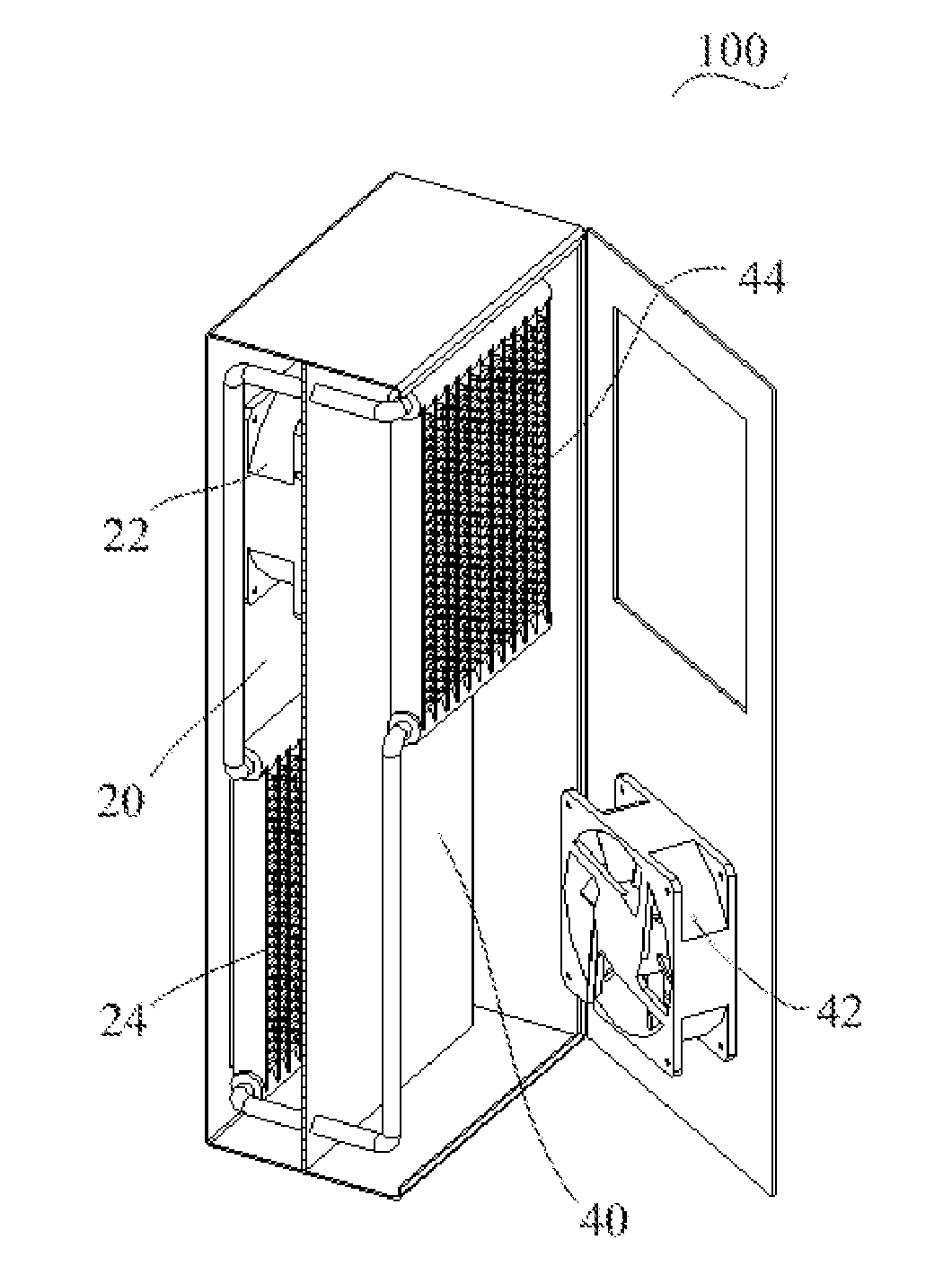
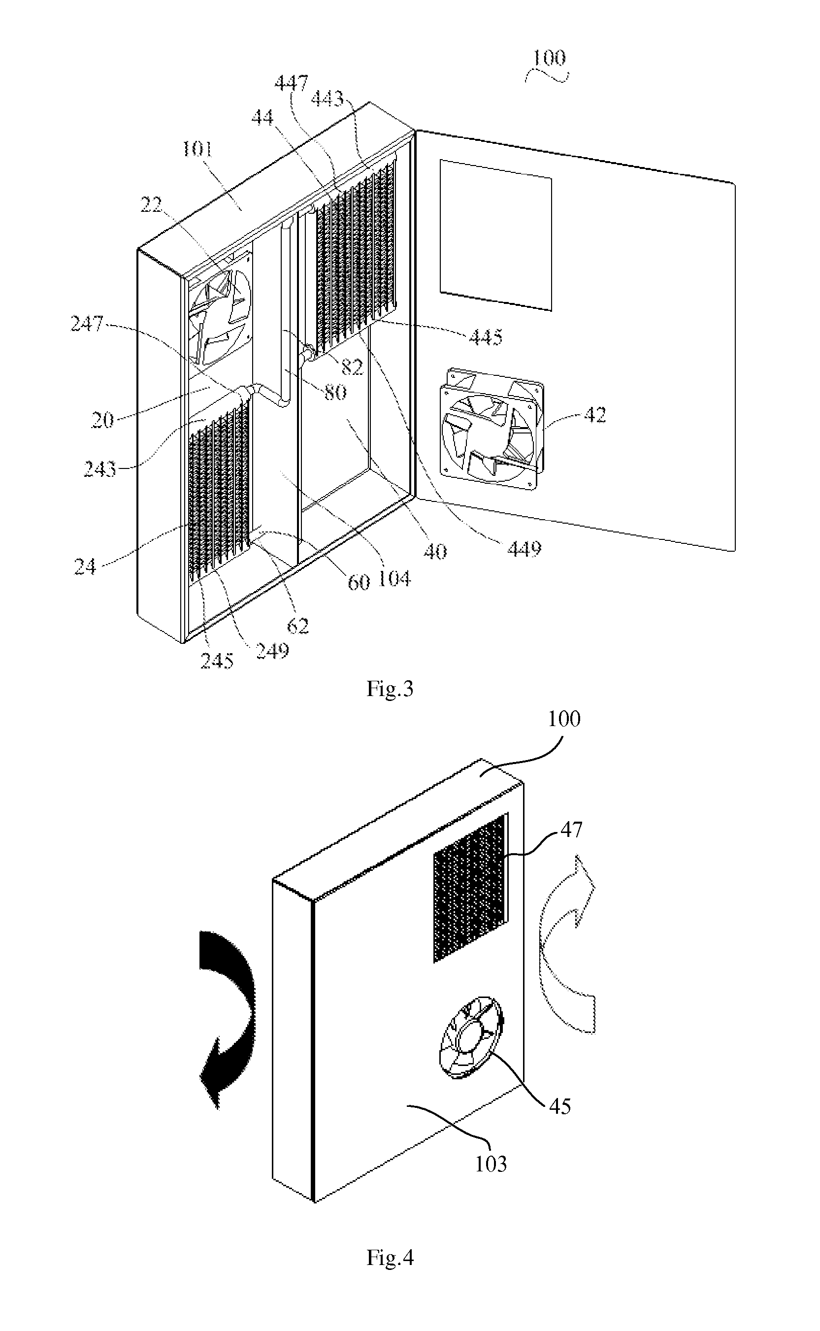
[0026]Referring to FIGS. 3, 6 and 7, wherein FIG. 3 is a three-dimensional structure diagram of a heat exchanger according to an embodiment of the present invention, FIG. 6 is a schematic diagram of a first group of dissipation tubules, and FIG. 7 is a partial enlarged diagram of Part A as illustrated in FIG. 6. The heat exchanger 100 includes a first air passage 20 and a second air passage 40. The first air passage 20 and the second air passage 40 are separated from each other, and the first air passage 20 is provided with a first fan unit 22 and a first group of heat dissipation tubules 24, and the second air passage 40 is provided with a second fan unit 42 and a second group of heat dissipation tubules 44. The upper ends 247 of the first group of heat dissipation tubules 24 along the gravity direction are communicated via a steam manifold 80 with the upper ends 447 of the second group of heat dissipation tubules 44 along the gravity direction. The lower ends 249 of the first grou...

embodiment 2

[0061]Referring to FIG. 11, which is a schematic diagram of a heat dissipation method of a heat exchanger according to an embodiment of the present invention.

[0062]The heat dissipation method of the heat exchanger includes the following steps.

[0063]In step 201, under the action of the first fan unit, the air inside the communication apparatus passes the first air passage, and under the action of the second fan unit, the air outside the communication apparatus passes the second air passage, wherein the first and second air passages are separated from each other.

[0064]In step 202, a heat exchange is carried out between the liquid in the first group of heat dissipation tubules and the air inside the communication apparatus passing the first air passage, so that the liquid in the first group of heat dissipation tubules is vaporized into steam by absorbing heat, and the steam flows along the steam manifold to the second group of heat dissipation tubules.

[0065]In step 203, a heat exchange...

embodiment 3

[0068]A communication apparatus is also provided according to an embodiment of the present invention. The communication apparatus includes a heat exchanger 100 and a cabinet. The cabinet is provided with a single board and the heat exchanger 100 is disposed in the cabinet. Referring to FIG. 3, the heat exchanger 100 includes a first air passage 20 and a second air passage 40. The first air passage 20 and the second air passage 40 are separated from each other. And the first air passage 20 is communicated with the air inside the cabinet (an internal circulation air passage may be formed), and the second air passage 40 is communicated with the air outside the cabinet (an external circulation air passage may be formed). The first air passage 20 is provided with a first fan unit 22 and a first group of heat dissipation tubules 24, and the second air passage 40 is provided with a second fan unit 42 and a second group of heat dissipation tubules 44. The upper ends 247 of the first group o...


PUM


Abstract

A heat exchanger, a heat dissipation method and a communication apparatus are provided. The heat exchanger includes a first and a second air passage separated from each other. The first air passage has a first fan unit and a first group of heat dissipation tubules. The second air passage has a second fan unit and a second group of heat dissipation tubules. The upper ends of the first and second group of heat dissipation tubules are communicated with each other via a steam manifold. The lower ends of the first and second group of heat dissipation tubules are communicated with each other via a liquid manifold. A closed pipeline filled with liquid vaporized when heated, is formed by the first and second group of dissipation tubules, the steam manifold and the liquid manifold. Heat dissipation fins are set among the first and second group of dissipation tubules.

Description

CROSS-REFERENCE TO RELATED APPLICATIONS[0001]This application claims priority to Chinese Patent Application No. 200910107884.X, entitled “heat exchanger, heat dissipation method of the same and communication apparatus”, and filed on Jun. 15, 2009, which is hereby incorporated by reference in its entirety.FIELD OF THE INVENTION[0002]The present invention relates to the field of heat dissipation technique, and particularly, to a heat exchanger, a heat dissipation method of the same and a communication apparatus.BACKGROUND OF THE INVENTION[0003]With the development of the communication technique, the integration level of the communication apparatus is increasingly higher, and the heat consumption in the unit space is continuously increased. Meanwhile, in order to meet the market demand in the communication field, the application arrange of the communication apparatus becomes more and more extensive. For an outdoor communication apparatus, the most prominent feature is that the communic...

Claims


Application Information

Patent Timeline
IPC IPC(8): H05K7/20F28F13/06F28F3/12F28D15/04
CPCF28D15/0266H05K7/202G06F1/20
Inventor FENG, TAQINGHONG, YUPINGLIN, HUIPENG, FENGZHANG, YUNHULWU, CHONG
Owner HUAWEI TECH CO LTD
Why Eureka
Try Eureka