
PATTERNED PERPENDICULAR MAGNETIC RECORDING MEDIUM WITH EXCHANGE-COUPLED COMPOSITE RECORDING STRUCTURE OF A FePt LAYER AND A Co/X MULTILAYER

Inactive Publication Date: 2012-06-14
HITACHI GLOBAL STORAGE TECH NETHERLANDS BV
View PDF8 Cites 18 Cited by
  • Summary
  • Abstract
  • Description
  • Claims
  • Application Information

AI Technical Summary

Benefits of technology

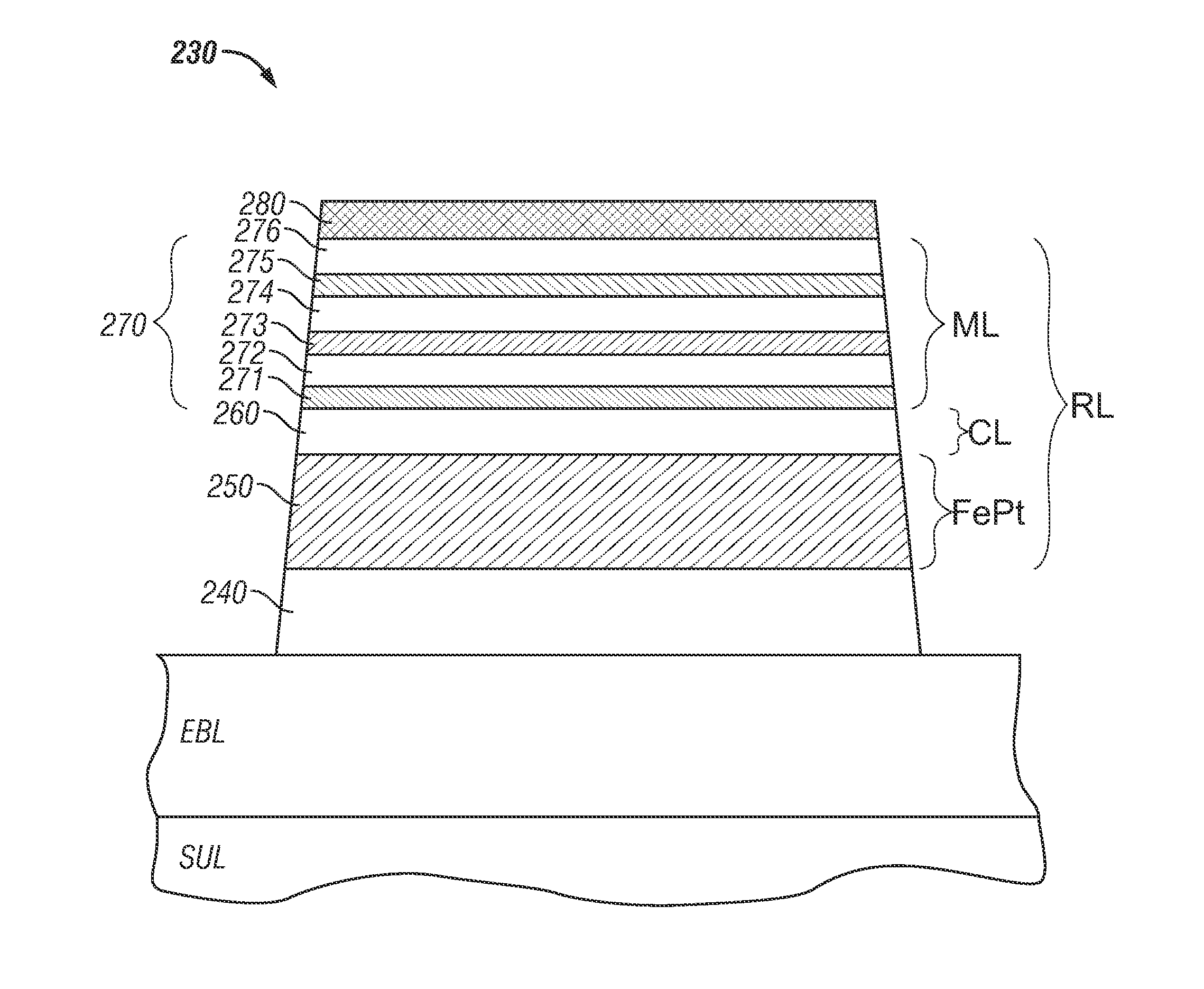
[0010]This invention relates to bit-patterned media (BPM) wherein the recording layer (RL) in the discrete magnetic islands is an exchange-coupled composite (ECC) structure with a high-Hk chemically-ordered FePt alloy lower layer, a lower-Hk Co/X laminate or multilayer (ML) upper layer with perpendicular magnetic anisotropy, wherein X is Pt, Pd or Ni, and an optional nonmagnetic separation layer or coupling layer (CL) between the FePt layer and the ML. The hard (high_Hk) FePt layer is preferably the chemically-ordered equiatomic binary alloy FePt based on the L10 phase, but may also be a pseudo-binary alloy based on the FePt L10 phase, e.g., (Fe(y)Pt(100−y))-X, where y is between about 45 and 55 atomic percent and the element X may be Ni, Au, Cu, Pd or Ag and is present in the range of between about 0% to about 20% atomic percent. The FePt alloy layer is sputter deposited onto a seed layer structure, like a CrRu/Pt bilayer, w

Problems solved by technology

Another critical issue for the development of BPM is that the switching field distribution (SFD) (i.e., the island-to-island variation of the coercive field) needs to be narrow enough to insure exact addressability of individual islands without overwriting adjacent islands.
Additionally, it has been found that the SFD broadens (that is, the bit-to-bit variation in the coercive field increases) as the size of the magnetic islands is reduced, which limits the achievable bit areal density of BPM.

Method used


Image

  • PATTERNED PERPENDICULAR MAGNETIC RECORDING MEDIUM WITH EXCHANGE-COUPLED COMPOSITE RECORDING STRUCTURE OF A FePt LAYER AND A Co/X MULTILAYER
  • PATTERNED PERPENDICULAR MAGNETIC RECORDING MEDIUM WITH EXCHANGE-COUPLED COMPOSITE RECORDING STRUCTURE OF A FePt LAYER AND A Co/X MULTILAYER
  • PATTERNED PERPENDICULAR MAGNETIC RECORDING MEDIUM WITH EXCHANGE-COUPLED COMPOSITE RECORDING STRUCTURE OF A FePt LAYER AND A Co/X MULTILAYER

Examples


Embodiment Construction

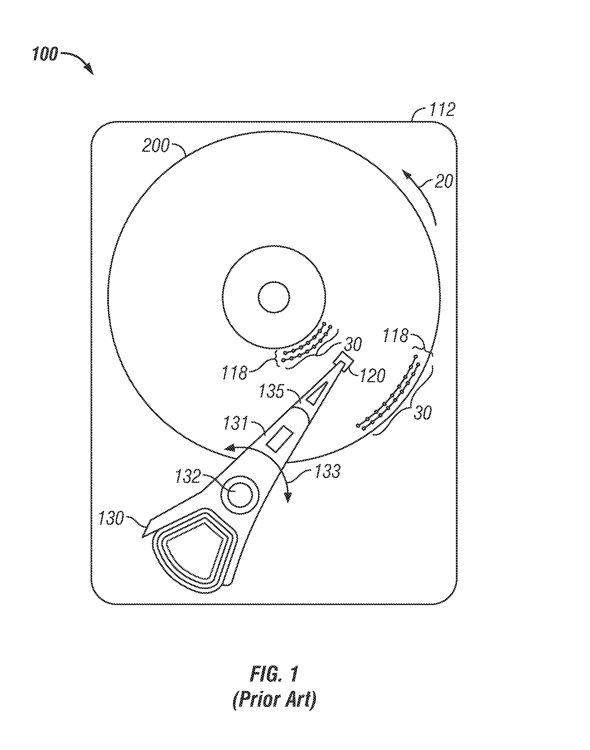
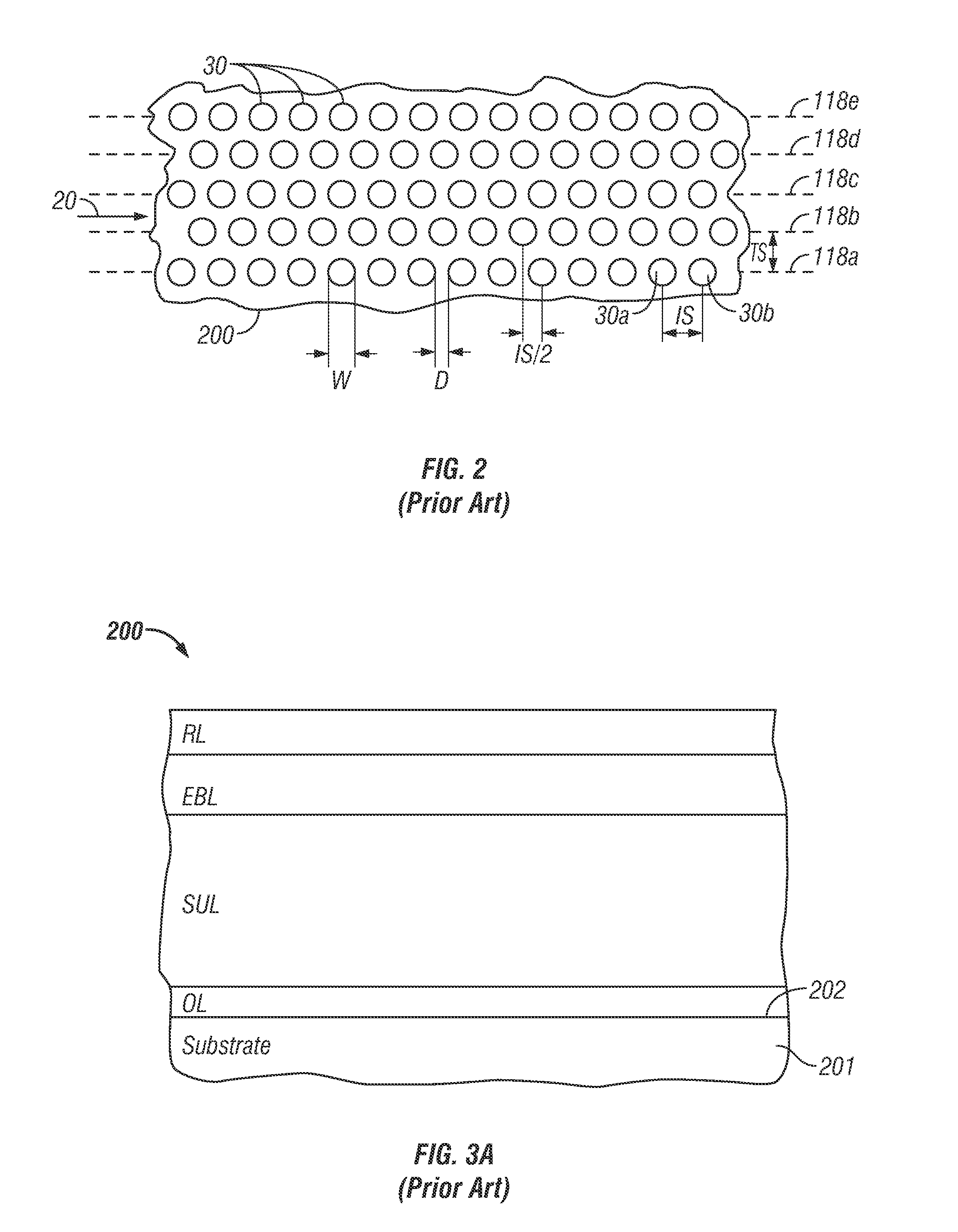
[0020]FIG. 1 is a top view of a patterned-media magnetic recording disk drive 100 with a patterned-media magnetic recording disk 200. The drive 100 has a housing or base 112 that supports an actuator 130 and a drive motor for rotating the magnetic recording disk 200. The actuator 130 may be a voice coil motor (VCM) rotary actuator that has a rigid arm 131 and rotates about pivot 132 as shown by arrow 133. A head-suspension assembly includes a suspension 135 that has one end attached to the end of actuator arm 131 and a head carrier, such as an air-bearing slider 120, attached to the other end of suspension 135. The suspension 135 permits the slider 120 to be maintained very close to the surface of disk 200 and enables it to “pitch” and “roll” on the air-bearing generated by the disk 200 as it rotates in the direction of arrow 20. A magnetoresistive read head (not shown) and an inductive write head (not shown) are typically formed as an integrated read / write head patterned as a serie...


PUM


Abstract

A bit-patterned media (BPM) magnetic recording disk has discrete data islands with an exchange-coupled composite (ECC) recording layer (RL) formed of a high-anisotropy chemically-ordered FePt alloy lower layer, a lower-anisotropy Co / X laminate or multilayer (ML) upper layer with perpendicular magnetic anisotropy, wherein X is Pt, Pd or Ni, and an optional nonmagnetic separation layer or coupling layer (CL) between the FePt layer and the ML. The FePt alloy layer is sputter deposited onto a seed layer structure, like a CrRu / Pt bilayer, while the disk substrate is maintained at an elevated temperature to assure the high anisotropy field Hk is achieved. The high-temperature deposition together with the CrRu / Pt seed layer structure provide a very smooth surface for subsequent deposition of the ML (and optional CL). The separate Co / X ML has by itself a very narrow switching field distribution (SFD), so that the SFD of the ECC RL is much narrower than the SFD for the FePt layer alone.

Description

BACKGROUND OF THE INVENTION[0001]1. Field of the Invention[0002]This invention relates generally to patterned perpendicular magnetic recording media, such as disks for use in magnetic recording hard disk drives, and more particularly to patterned disks with data islands having improved magnetic recording properties.[0003]2. Description of the Related Art[0004]Magnetic recording hard disk drives with patterned magnetic recording media have been proposed to increase data density. In conventional continuous magnetic recording media, the magnetic recording layer is a continuous layer over the entire surface of the disk. In patterned media, also called bit-patterned media (BPM), the magnetic recording layer on the disk is patterned into small isolated data islands arranged in concentric data tracks. While BPM disks may be longitudinal magnetic recording disks, wherein the magnetization directions are parallel to or in the plane of the recording layer, perpendicular magnetic recording dis...

Claims


Application Information

Patent Timeline
IPC IPC(8): G11B5/667G11B11/00G11B5/127G11B5/66G11B5/65
CPCG11B5/66G11B5/7325G11B5/855G11B5/82G11B5/746G11B5/1278G11B5/7375G11B5/7368G11B5/7369G11B5/672G11B5/678
Inventor HELLWIG, OLAVMCCALLUM, ANDREW THOMASWELLER, DIETER K.
Owner HITACHI GLOBAL STORAGE TECH NETHERLANDS BV
Learn More