Device for Filtration of Fluids Therethrough and Accompanying Method

a technology of fluid filtration and fluid filtration, which is applied in the field of fluid filtration devices, can solve the problems of limited throughput, limited usefulness of in-line systems, and compounded problems, and achieve the effect of facilitating the separation and removal of target components

Active Publication Date: 2012-06-14
CHARLES STARK DRAPER LABORATORY +1
View PDF3 Cites 113 Cited by
  • Summary
  • Abstract
  • Description
  • Claims
  • Application Information

AI Technical Summary

Benefits of technology

[0010]The present invention is directed to a microfluidic device that facilitates the separation and removal of target components from a source fluid flowing in a source microfluidic channel without removing or altering other components in the source fluid. The fluid can be a liquid or a gas. The target components can be any particulate, molecule or cellular material that is magnetic or can be bound to a magnetic particle introduced to the flowing fluid. The source channel(s) can be connected to a collection microfluidic channel(s) by one or more transfer channels. A collection fluid, flowing in the collection channel(s) can be used to flush the target components out of the microfluidic device. A magnet or a magnetic source can be positioned adjacent the collection channel, or an external magnetic field gradient can be applied, to attract the magnetic target components or the target components bound to a magnetic particle into the transfer channels and into the collection channel(s) where they can be carried away in the collection fluid. The magnet or the magnetic field gradient source can be positioned relative to the collection channel(s) to permit the magnetic field gradient to draw the target components into the transfer channels and the collection channel, but not so strong as to cause the target components to lodge in the collection channel(s), unable to be flushed out by the flow of the collection fluid. As one of ordinary skill would appreciate, the position of the magnet or the source of the magnetic field gradient (in the case of an electromagnet) relative to the channels can be determined as a function of any or all of the following: the strength of the magnetic field and field gradient, the magnetic properties of the magnetic particles, the size of the target components and / or the magnetic particles, the size and / or shape of the channels, or the speed and / or viscosity of the fluids used.

Problems solved by technology

This limits their usefulness in in-line systems.
Moreover, existing methods typically operate at the macroscale, where diffusion distances require slower flow speeds, resulting in limited throughput.
This problem is compounded in single-channel devices.

Method used


Image

  • Device for Filtration of Fluids Therethrough and Accompanying Method
  • Device for Filtration of Fluids Therethrough and Accompanying Method
  • Device for Filtration of Fluids Therethrough and Accompanying Method

Examples


examples

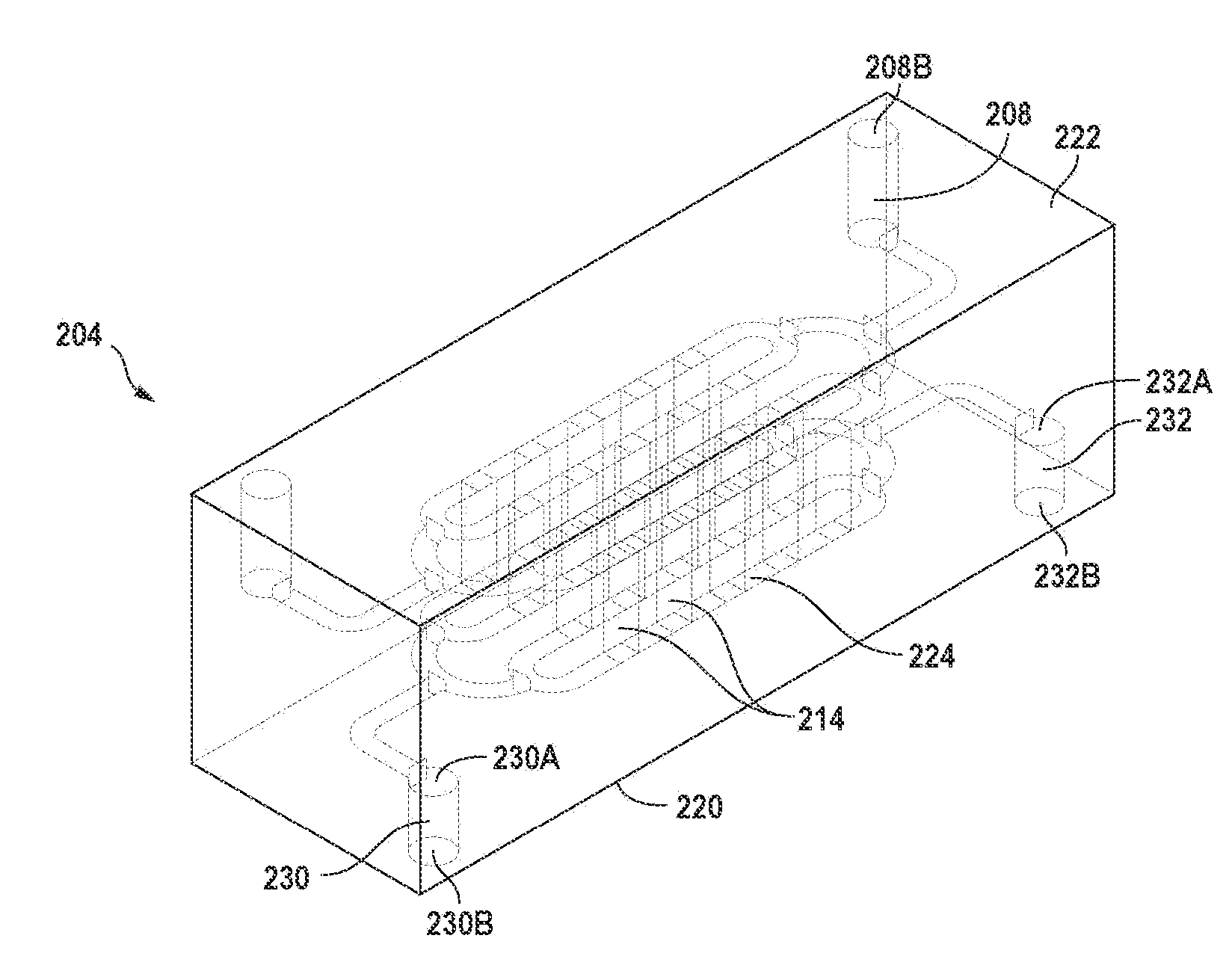
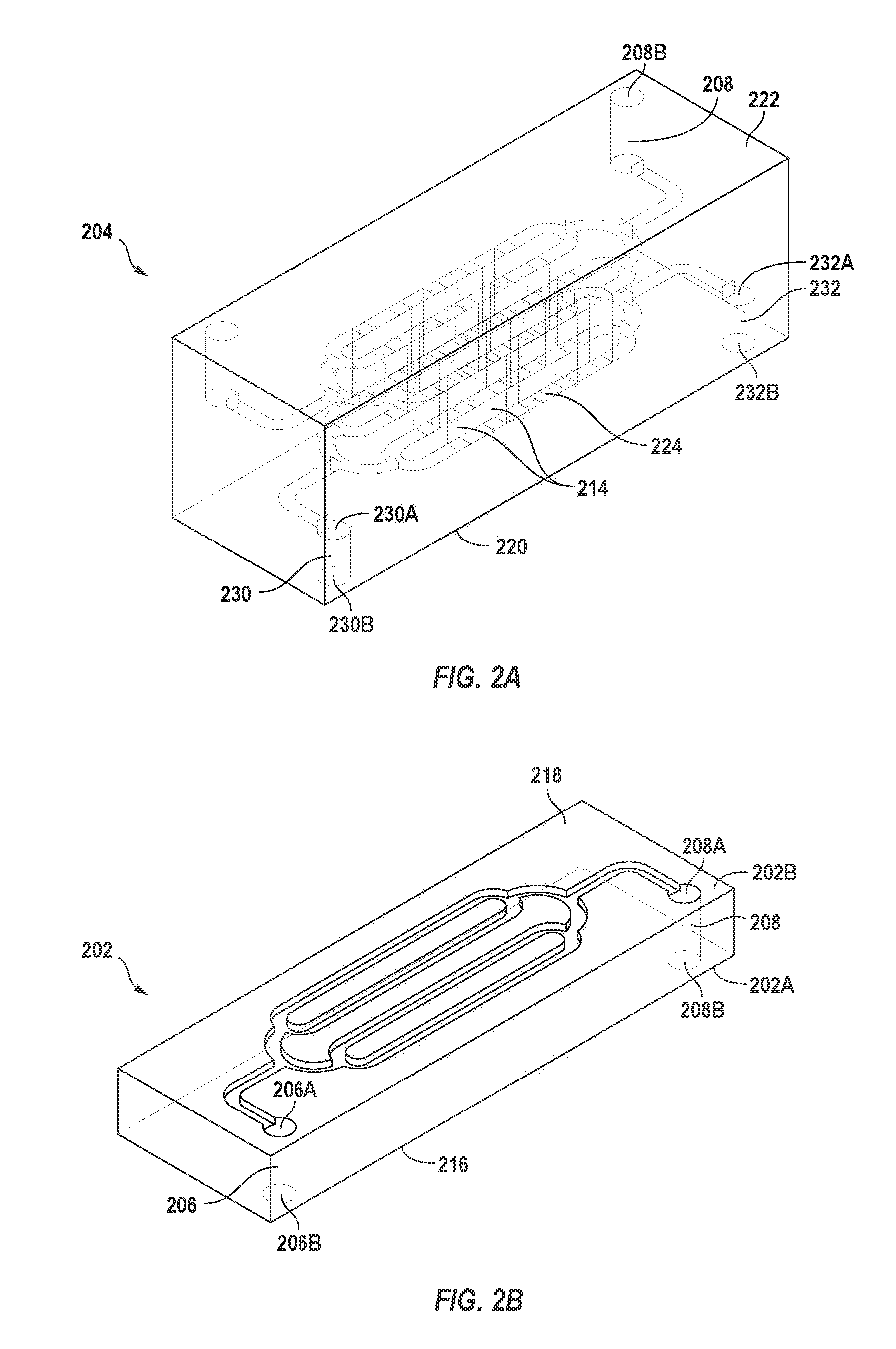
[0180]In a prototype system, six NiFeB magnets (6 mm×2 mm×2 cm; w×h×l) were stacked 2×3 with alternating magnetic field directions, such that the overall dimensions were (18 mm×4 mm×2 cm; w×h×l), before placing them adjacent to the microfluidic device. Alternatively, one NiFeB magnet or an electromagnet with appropriate field concentrator that can cover all the throughholes and exert the sufficient magnetic pulling forces (field gradient) could have been used. In the case of using permanent magnets, it was critical that the widest face of the magnets was facing the channels below because this face (18 mm×2 cm; w×l) has the highest magnetic flux and thus pulling strength. Using a six-magnet configuration, the magnetic field strength was approximately 50 mT-100 mT at a distance of 3 mm-5 mm, which was at the distance of the flowing fluid (blood) layer. The third layer of PDMS had the same network of channels facing down, but was connected to the blood fluid channels only by the transf...


PUM

PropertyMeasurementUnit
sizeaaaaaaaaaa
angleaaaaaaaaaa
depthaaaaaaaaaa

Abstract

A microfluidic device for separating target components from a source fluid includes one or more source channels connected to one or more collection channels by one or more transfer channels. The target components of the source fluid can be magnetic or bound to magnetic particles using a know binding agent. A source fluid containing magnetically bound target components can be pumped through the source channel of the microfluidic device. A magnetic field gradient can be applied to the source fluid in the source channel causing the magnetically bound target components to migrate through the transfer channel into the collection channel. The collection channel can include a collection fluid that is stagnant until a predefined volume of source fluid is processed or a predefined volume of target components accumulate in the collection channel, at which point collection fluid can be pumped into the collection channel to flush the target components out of the collection channel. The target components can be subsequently analyzed for detection and diagnosis.

Description

CROSS-REFERENCE TO RELATED APPLICATIONS[0001]This application claims any and all benefits as provided by law of U.S. Provisional Patent Application Ser. No. 61 / 144,897 filed on Jan. 15, 2009, the contents of which are incorporated herein by reference in their entirety.GOVERNMENT SUPPORT[0002]The subject matter described herein was made with support under grant number No. W81XWH-05-1-0115 awarded by the United States Department of Defense. The United States government has certain rights in the claimed subject matter.REFERENCE TO MICROFICHE APPENDIX[0003]Not ApplicableBACKGROUND[0004]1. Technical Field of the Invention[0005]The present invention is directed to fluidic devices that can be used to separate target components from flowing fluids. More specifically, the invention is directed to methods for and systems using fluidic and microfluidic devices to separate particulate, molecular and cellular material from a flowing fluid.[0006]2. Description of the Prior Art[0007]Chemical and b...

Claims


Application Information

Patent Timeline
Patent Type & Authority Applications(United States)
IPC IPC(8): B03C1/02C12Q1/68H01J49/26C12Q1/18C12M1/42G01N33/53C12Q1/02
CPCB03C1/01B03C1/288G01N33/54366G01N1/40G01N33/54326B03C2201/18B03C2201/26
Inventor YUNG, CHONG WINGINGBER, DONALD E.FIERING, JASON O.VARGHESE, MATHEW
Owner CHARLES STARK DRAPER LABORATORY
Why Eureka
Try Eureka