
Apparatus for monitoring a door with a 3D sensor

a technology of 3d sensors and accessories, applied in the direction of distance measurement, instruments, using reradiation, etc., can solve the problems of affecting the size of the area to be monitored may change, and the danger area to be monitored may become dangerous to users. , to achieve the effect of improving the convenience of mounting and/or installation

Active Publication Date: 2012-06-14
CEDES AG
View PDF11 Cites 11 Cited by
  • Summary
  • Abstract
  • Description
  • Claims
  • Application Information

AI Technical Summary

Benefits of technology

[0006]The object of the invention is therefore to provide an apparatus for monitoring a door with a 3D sensor, which apparatus improves the mounting and / or installation convenience in comparison with the prior art with reasonable costs.
[0007]The aim of the invention is to develop a universal monitoring sensor for automatic doors (revolving doors and double doors). In this case, the area to be monitored is intended to be easily and quickly adapted to the corresponding application and mounting position. The use of the TOF (Time-of-Flight) principle makes it possible to determine the distance of an object in the monitoring area as the third dimension. This makes it possible not only to monitor a precisely defined area but to set the sensor to a precisely defined monitoring volume using knowledge of the ambient conditions of the sensor. In this case, the sensor preferably consists of a compact unit which simultaneously comprises a transmitter and a receiver. In the first step, the scene to be monitored is illuminated using LEDs, for example. The emitted light is reflected and passes back into the sensor where it is detected using the receiving unit. The receiving part consists of a TOF chip with a plurality of pixels. Each pixel may receive a measurement beam reflected by an object. Modulated IR light is used for example. In order to determine the distance, a phase shift between the received signal and the emitted signal may be evaluated. The corresponding evaluation results in a distance value for each pixel, thus achieving a three-dimensional / volume-related capture image. The optics are designed in such a manner that the illumination remains focused in individual discrete beams, which results in corresponding spots with a high light intensity.
[0009]In an apparatus for monitoring a door with a 3D sensor which is able to detect distances to an object in the monitoring area as the third dimension, the 3D sensor being arranged in a housing, and immovably arranged transmission means for transmitting a measurement beam and receiver means for receiving the reflected measurement beam being provided in the housing, one aspect of the invention is that provision is made of a control unit which is designed to obtain information relating to the position of the apparatus, and the control unit evaluates the measurement beam on the basis of an item of position information. As a result, the mounting of a monitoring apparatus can be simplified and can be made more reliable. This is because, with an item of position information, the apparatus can unambiguously assign measurement beams detected after mounting to the environment and can thus also correctly evaluate said beams. In addition, it is possible for the apparatus to align itself as it were after mounting. For example, the control unit is designed to determine a mounting height of the apparatus after mounting by evaluating the measurement beam on the basis of the item of position information. It is thus no longer necessary to input a mounting height in order to calibrate the apparatus.
[0010]In one preferred refinement of the invention, the control unit is also designed to use a height of the mounting location as a parameter for defining the monitoring area. In order to be able to completely define the monitoring area, it is then only still necessary to specify the width of the monitoring area in the case of conventional double doors. Mounting and input errors can thus be minimized.
[0014]The practice of specifying a basic position and at least two further mounting positions, which are in the form of defined positions, makes it considerably easier for an installer to mount and orient a corresponding 3D sensor, as a result of which positioning errors and resultant malfunctions are avoided.
[0017]In order to achieve a high resolution of the 3D sensor, it is also proposed that the 3D sensor in a housing comprises a receiver array and / or a sensor array. A receiver array makes it possible to evaluate a large number of measurement beams, in particular at the same time, in which case a transmitter array can be used to scan a comparatively large area, in particular with a plurality of measurement beams.

Problems solved by technology

Automatic doors and revolving doors may become dangerous to users if their danger zones in front of the door leaf are not monitored.
Since the dangerous components move during the opening and closing process, the danger area to be monitored also concomitantly moves.
Furthermore, the size of the area to be monitored must possibly change during movement.
However, such sensors are very complex and are therefore associated with considerable production costs.
In addition, these sensors provide considerably restricted convenience during installation and adaptation to the monitoring area since a multiplicity of optical components have to be aligned.

Method used


Image

  • Apparatus for monitoring a door with a 3D sensor
  • Apparatus for monitoring a door with a 3D sensor
  • Apparatus for monitoring a door with a 3D sensor

Examples


Embodiment Construction

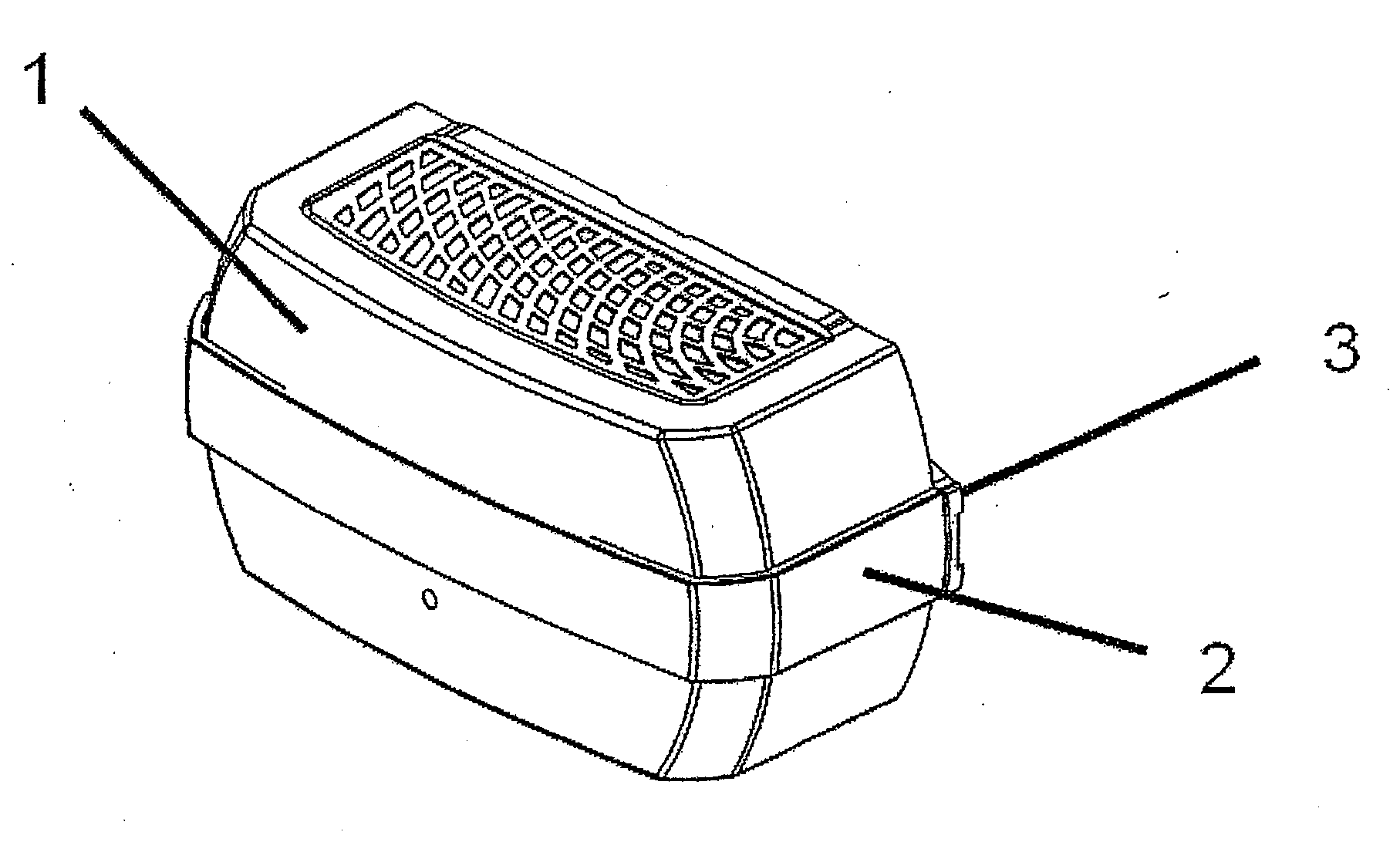
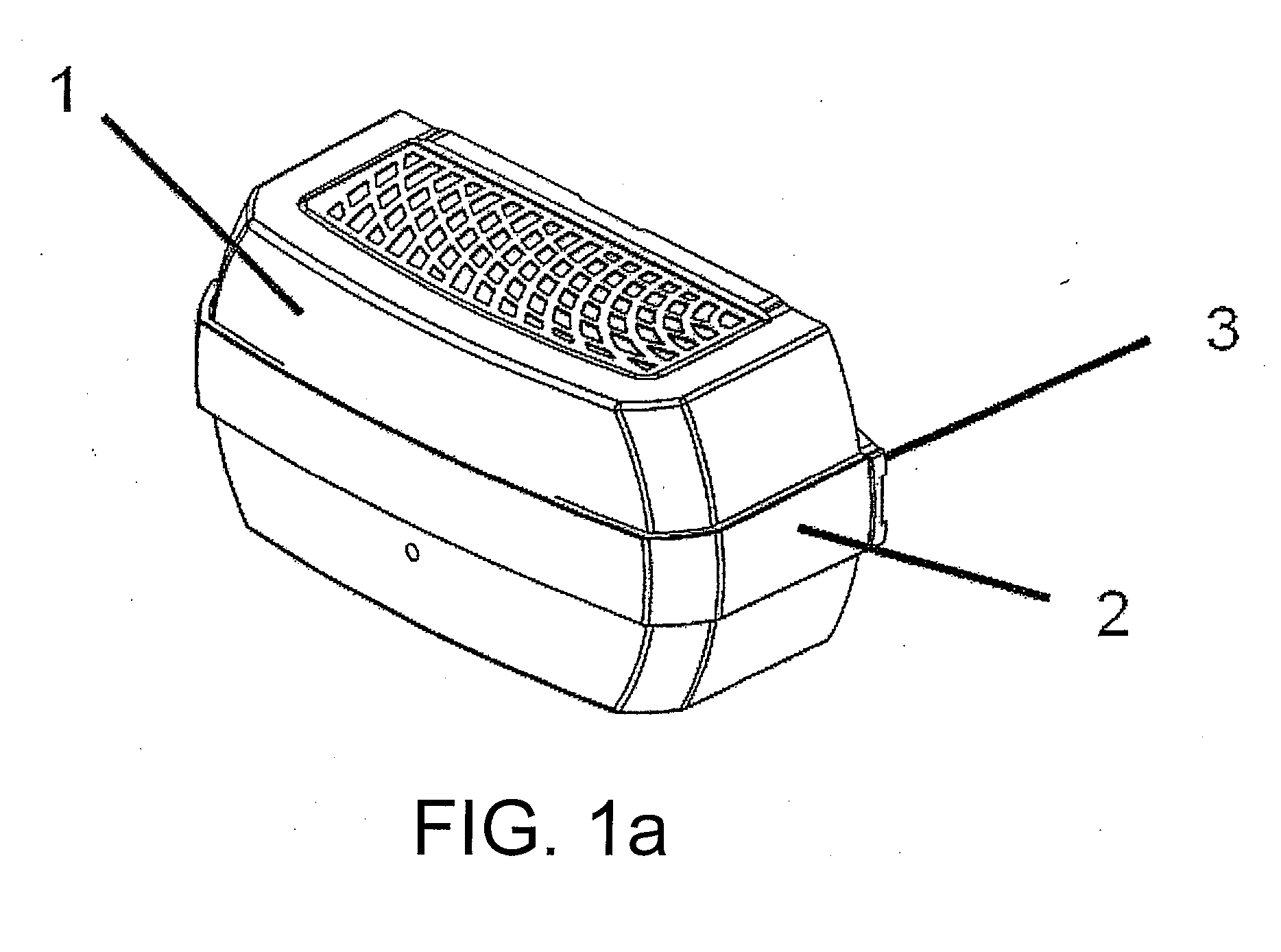
[0030]In detail, FIG. 1a shows an illustration of a housing 1 for an apparatus according to the invention for monitoring a door. The housing 1 is at least partially surrounded by a mounting frame 2 which engages in a mounting plate 3 on the rear side of the housing 1. In this manner, the housing 1 is held on the mounting means formed by the mounting frame 2 and the mounting plate 3.

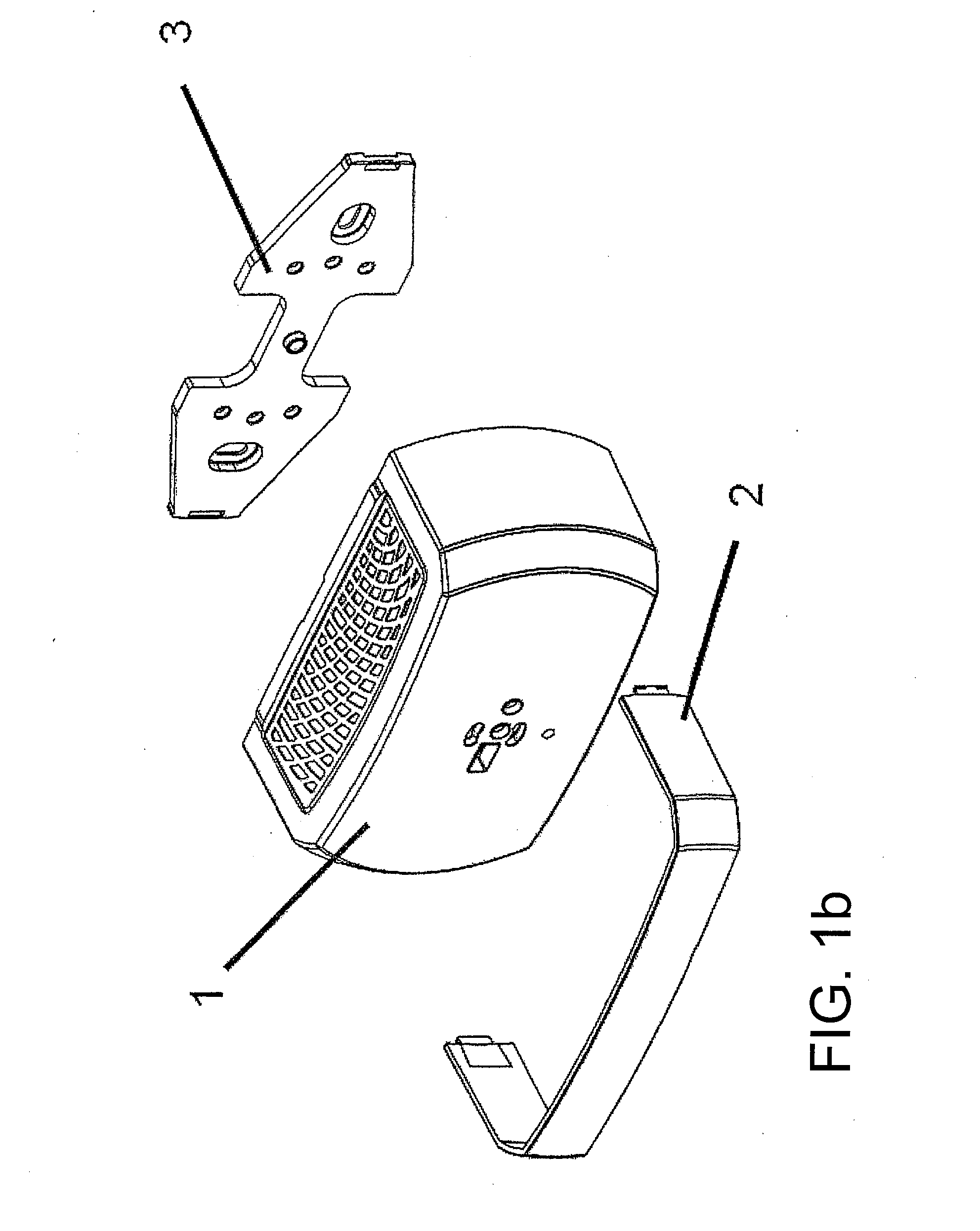
[0031]FIG. 1b shows an exploded illustration of the following parts: the housing 1, the mounting frame 2 and the mounting plate 3.

[0032]FIG. 2a shows a frontal view of the arrangement according to FIG. 1a. The housing 1 has a design corresponding to a segment of a circle on its right-hand and left-hand outer sides, the radius being adapted by the mounting frame, in particular in a manner matched to its inner side.

[0033]FIG. 2b shows a first pivoted position of the housing 1 in the mounting frame 2, the underside of the housing, on which the signals needed to monitor a door are emitted, being illustrated i...


PUM


Abstract

An apparatus for monitoring a door with a 3D sensor which is able to detect distances to an object in the monitoring area as the third dimension, the 3D sensor being arranged in a housing, and immovably arranged transmission means for transmitting a measurement beam and receiver means for receiving a reflected measurement beam being provided in the housing, characterized in that provision is made of a control unit which is designed to obtain an item of information relating to the position of the apparatus, and in that the control unit evaluates the measurement beam on the basis of an item of position information.

Description

[0001]This application claims the benefit under 35 USC §119(a)-(d) of European Application No. 10 014 616.6 filed Nov. 15, 2010, the entirety of which is incorporated herein by reference.FIELD OF THE INVENTION[0002]The invention relates to an apparatus for monitoring a door with a 3D sensor.BACKGROUND OF THE INVENTION[0003]Automatic doors and revolving doors may become dangerous to users if their danger zones in front of the door leaf are not monitored. Since the dangerous components move during the opening and closing process, the danger area to be monitored also concomitantly moves. Furthermore, the size of the area to be monitored must possibly change during movement. This results in the need to concomitantly move the monitoring sensor with the dangerous component, in which case adaptation to the wide variety of different door sizes and required monitoring areas is desirable. Economic factors also require the provision of a universal sensor with monitoring properties which can be...

Claims


Application Information

Patent Timeline
IPC IPC(8): G06F15/00G01S17/04G01S17/89
CPCF16M11/06F16P3/147F16P3/141G01S7/4813G01S7/4972G01S17/026G01S17/88G01S17/89E05F15/43E05F15/73G01B21/16G01C3/00E05Y2900/132F16P3/14F16P3/142F16M13/02G01S17/04
Inventor COI, BEAT DE
Owner CEDES AG
Learn More