
Method and Tooling for Partial Disassembly of a Bypass Turbofan Engine

a technology of bypass turbofan and disassembly method, which is applied in the direction of manufacturing tools, machines/engines, rigid support of bearing units, etc., can solve the problem of high cost of disassembly of engines from aircraft, and achieve the effect of facilitating the interlocking construction of the nozzle assembly and the rotation of the low pressure turbine modul

Active Publication Date: 2012-06-21
TURBINE TOOLING SOLUTIONS
View PDF3 Cites 49 Cited by
  • Summary
  • Abstract
  • Description
  • Claims
  • Application Information

AI Technical Summary

Benefits of technology

[0005]In one embodiment, the low pressure turbine horizontal removal tool permits rotational freedom of the low pressure turbine module about the module's longitudinal axis.
[0006]In another embodiment, the low pressure turbine horizontal removal tool facilitates rotation of the low pressure turbine module longitudinal axis from horizontal to vertical.
[0007]In another embodiment, the nozzle assembly is placed in a nozzle assembly jig adapted to properly position the plurality of interlocked nozzle segments and feather seals, and the nozzle assembly jig facilitates the interlocked construction of the nozzle assembly from individual nozzle segments and feather seals.
[0019]Another embodiment has a first stage high pressure turbine nozzle assembly retaining tool. The nozzle assembly is comprised of a plurality of interlocked nozzle segments and feather seals. The first stage nozzle assembly retaining tool secures the nozzle assembly such that the plurality of nozzle segments and feather seals remain interlocked upon removal. The embodiment also has a nozzle assembly jig adapted to properly position the plurality of interlocked nozzle segments and feather seals. The nozzle assembly jig facilitating the interlocked construction of the nozzle assembly from the nozzle segments and feather seals.

Problems solved by technology

Removal of an engine from an aircraft is expensive in that it requires not only the investment in disconnecting and reconnecting the engine from the aircraft but it may also require a test flight of the aircraft once the engine has been reattached.

Method used


Image

  • Method and Tooling for Partial Disassembly of a Bypass Turbofan Engine
  • Method and Tooling for Partial Disassembly of a Bypass Turbofan Engine
  • Method and Tooling for Partial Disassembly of a Bypass Turbofan Engine

Examples


Embodiment Construction

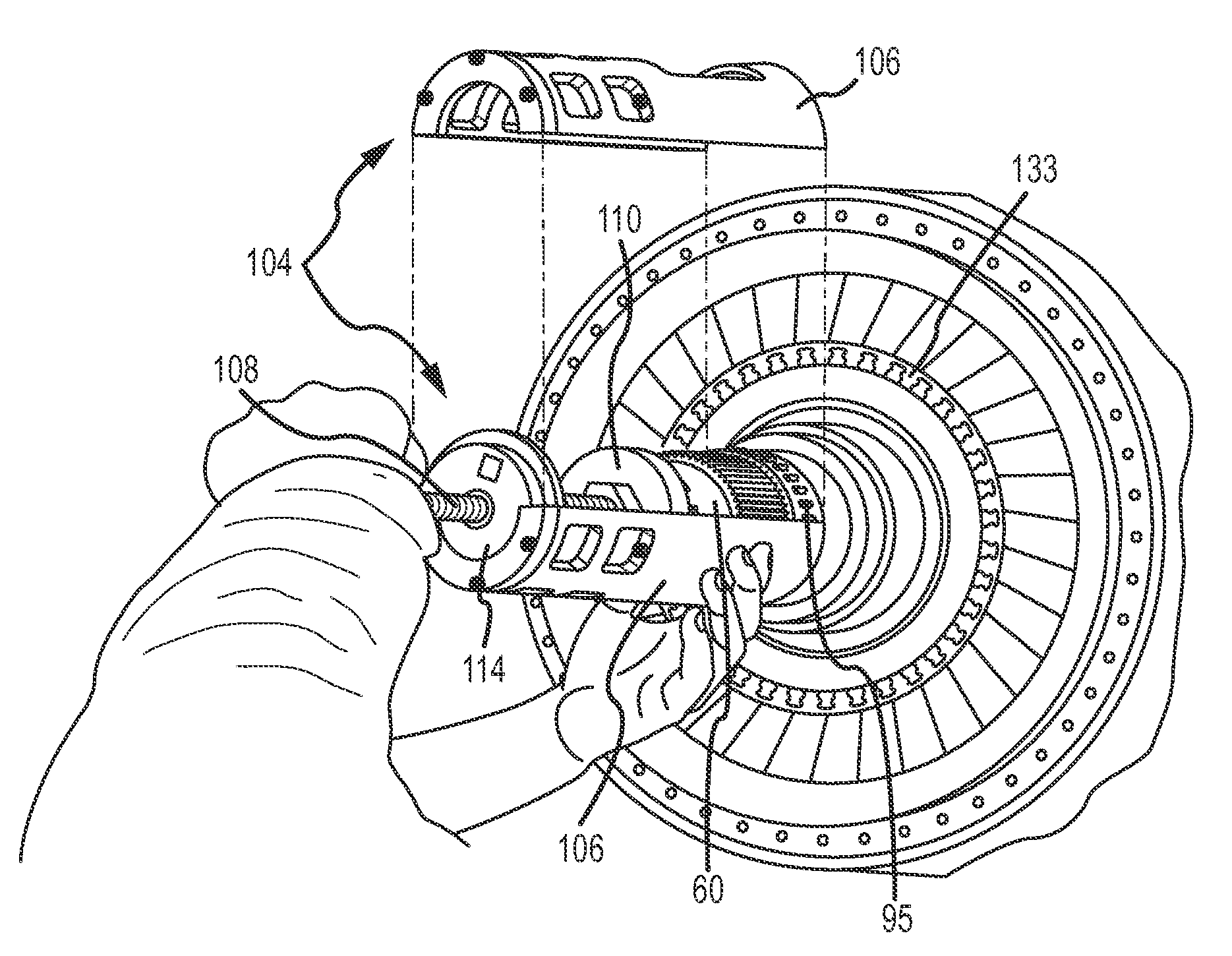
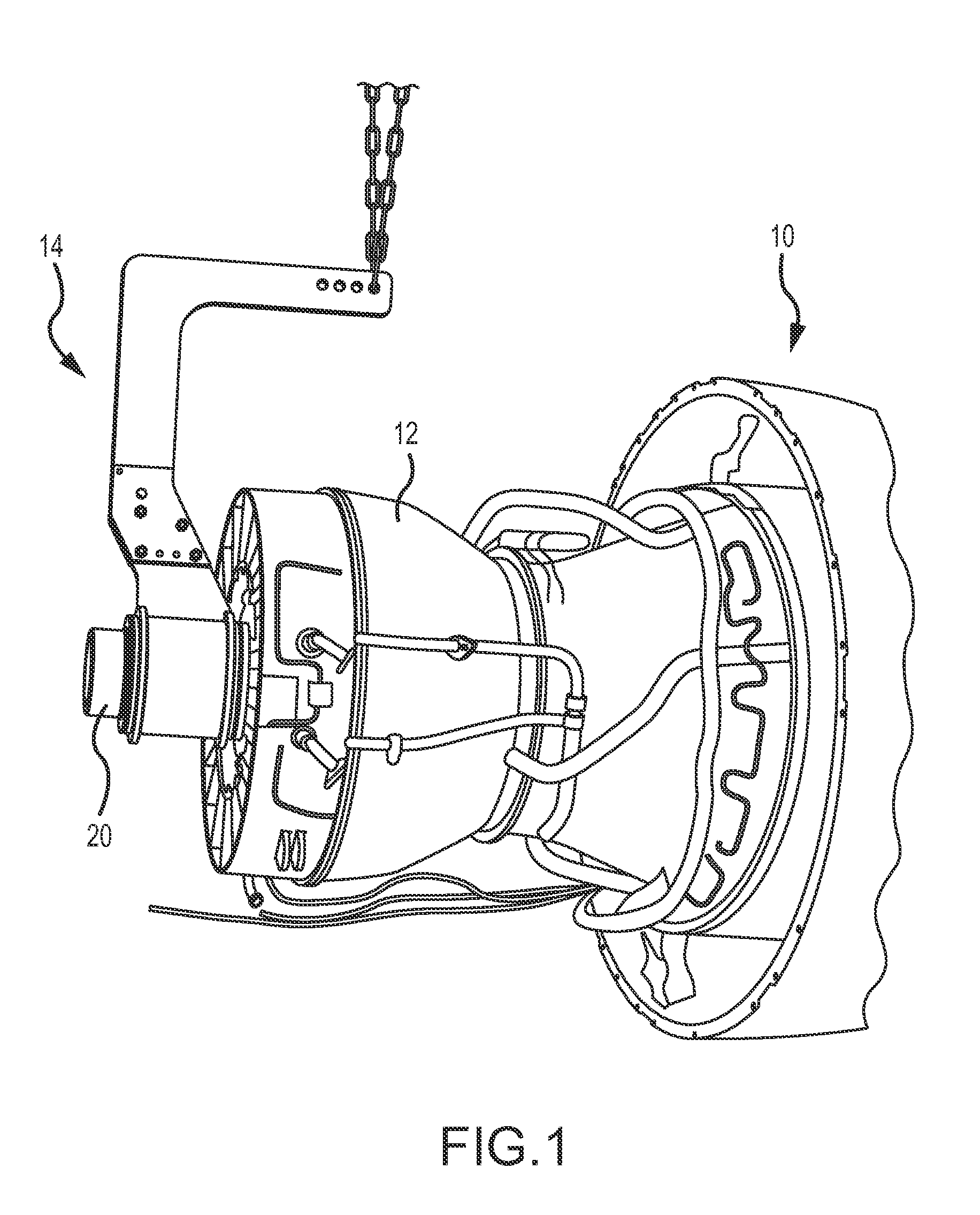
[0057]Horizontal disassembly of an engine(10) such as the HTF 7000 from the rear requires removal of the aft sump(not shown) and number 5 bearing(not shown) as is conventionally known. Next, the low-pressure turbine module(12) may be removed. FIG. 1 depicts a horizontal low-pressure turbine module removal tool(14) connected to the low-pressure turbine module(12) with the low-pressure turbine module(12) attached to the remainder of the engine(10). The engine's(10) longitudinal axis is generally horizontal.

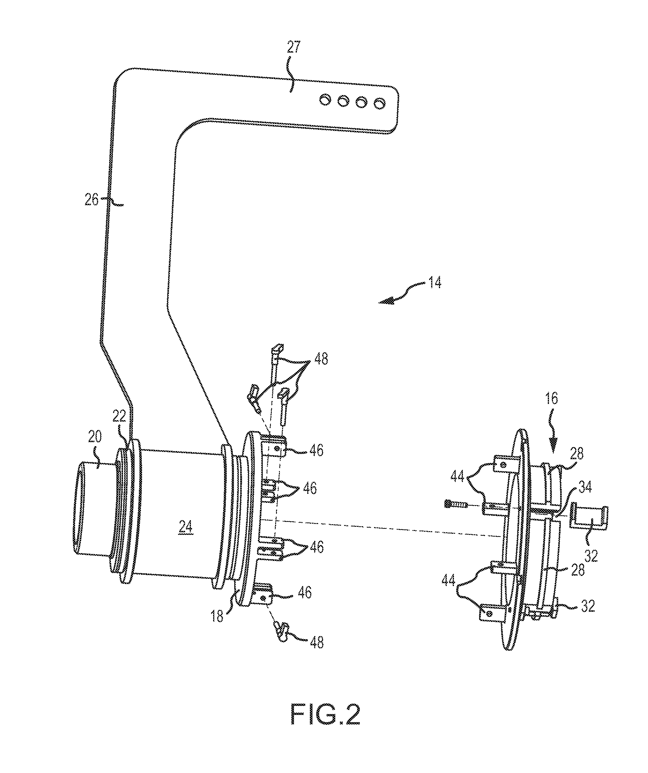
[0058]FIG. 2 depicts an embodiment of the horizontal low-pressure module removal tool(14). In one embodiment, the tool(14) has a detachable low-pressure turbine module attachment member(16), a hub(18) connected to a shaft(20) that rotationally engages a friction reducing insert(22) interposed between the shaft(20) and a cylindrical insert housing(24) that is connected to a vertical support member(26). The friction reducing insert(22) may be made of any material minimizing friction b...


PUM

PropertyMeasurementUnit
Forceaaaaaaaaaa
Pressureaaaaaaaaaa
Gravityaaaaaaaaaa

Abstract

A method and tooling for partial disassembly of a bypass turbofan engine wherein the longitudinal axis of the bypass turbofan engine remains generally horizontal during disassembly. The low pressure turbine module is removed with a low pressure turbine module horizontal removal tool. An extended bearing nut tool may be supported by a stabilization member and may remove a bearing nut. An extended high pressure turbine shaft stretching tool may stretch a high pressure turbine shaft to release a high pressure turbine shaft nut. An extended bearing pulling tool may be used to pull a bearing while the low pressure turbine shaft remains in place. A modified measurement bridge may be used to measure the position of certain components while the low pressure turbine shaft remains in place. A nozzle jig may be used to assemble nozzles and feather seals to create a nozzle module. And an arcuate datum may be used to make certain measurements from the aft end of the high pressure turbine shaft while the low pressure turbine shaft remains in place.

Description

BACKGROUND OF THE INVENTION[0001]The Honeywell HTF 7000 bypass turbofan engine is typical of the engines used on commercial business jets. Business jet engines require periodic inspection and repair that may require removal of the engine from the aircraft.[0002]Removal of an engine from an aircraft is expensive in that it requires not only the investment in disconnecting and reconnecting the engine from the aircraft but it may also require a test flight of the aircraft once the engine has been reattached. Typically, conventional inspection or repair of the aft portion of the HTF 7000 engine required that the engine be removed from the aircraft. The inlet spinner was removed from the engine and the engine was positioned with the longitudinal axis being vertical and the inlet portion of the engine being down. Thus positioned, the engine could be disassembled from the aft and relevant portions of the engine could be inspected and repaired as needed.[0003]While disassembly of the HTF 70...

Claims


Application Information

Patent Timeline
IPC IPC(8): B25B27/00B23P11/00B23P19/06B23P17/00
CPCB25B27/062F01D25/285F05D2230/70Y10T29/53909Y10T29/53991Y10T29/49822B25B27/0035F16C35/00
Inventor THOMAS, ERIK C.
Owner TURBINE TOOLING SOLUTIONS
Learn More