
Method And Apparatus For Reducing Residual Torque And Neps In Singles Ring Yarns

a technology of residual torque and neps, which is applied in the direction of yarn, continuous wounding machines, textiles and papermaking, etc., can solve the problems of yarn appearance degradation, achieve low cost of investment and maintenance, reduce the effect of neps and residual torqu

Active Publication Date: 2012-06-21
THE HONG KONG POLYTECHNIC UNIV
View PDF21 Cites 22 Cited by
  • Summary
  • Abstract
  • Description
  • Claims
  • Application Information

AI Technical Summary

Benefits of technology

[0015]Therefore, it is an objective of the present invention to provide an improved method and apparatus for producing singles ring yarns. The method and apparatus have the actual advantages of easy yarn piecing-up and doffing process, low spinning end breakage when using ordinary fibers and low cost of investment and maintenance. The method is thus not only able to meet the commercial requirements of the large-scale production in the textile industry but also possesses high false twist efficiency. Instead of one twisting point, two twisting points are adopted for the yarn false twisting to improve the false twist efficiency. Also, the false twist efficiency is controlled such that the desirable lower residual torque as well as other yarn properties can be achieved. Accordingly, a ratio of the velocity of the belt to the delivery speed of the yarn is controlled and the wrapping angle of the yarn on the belts is adjusted in order to obtain the desired property of the final singles ring yarn.

Problems solved by technology

While those low-twist and low-torque methods are capable of producing satisfactory results in low-end products, they can cause appearance deterioration of the yarns, for example, unsatisfactory high numbers of neps, thick and thin places will present a problem in high-quality yarn products (see Table 1).

Method used


Image

  • Method And Apparatus For Reducing Residual Torque And Neps In Singles Ring Yarns
  • Method And Apparatus For Reducing Residual Torque And Neps In Singles Ring Yarns
  • Method And Apparatus For Reducing Residual Torque And Neps In Singles Ring Yarns

Examples


Embodiment Construction

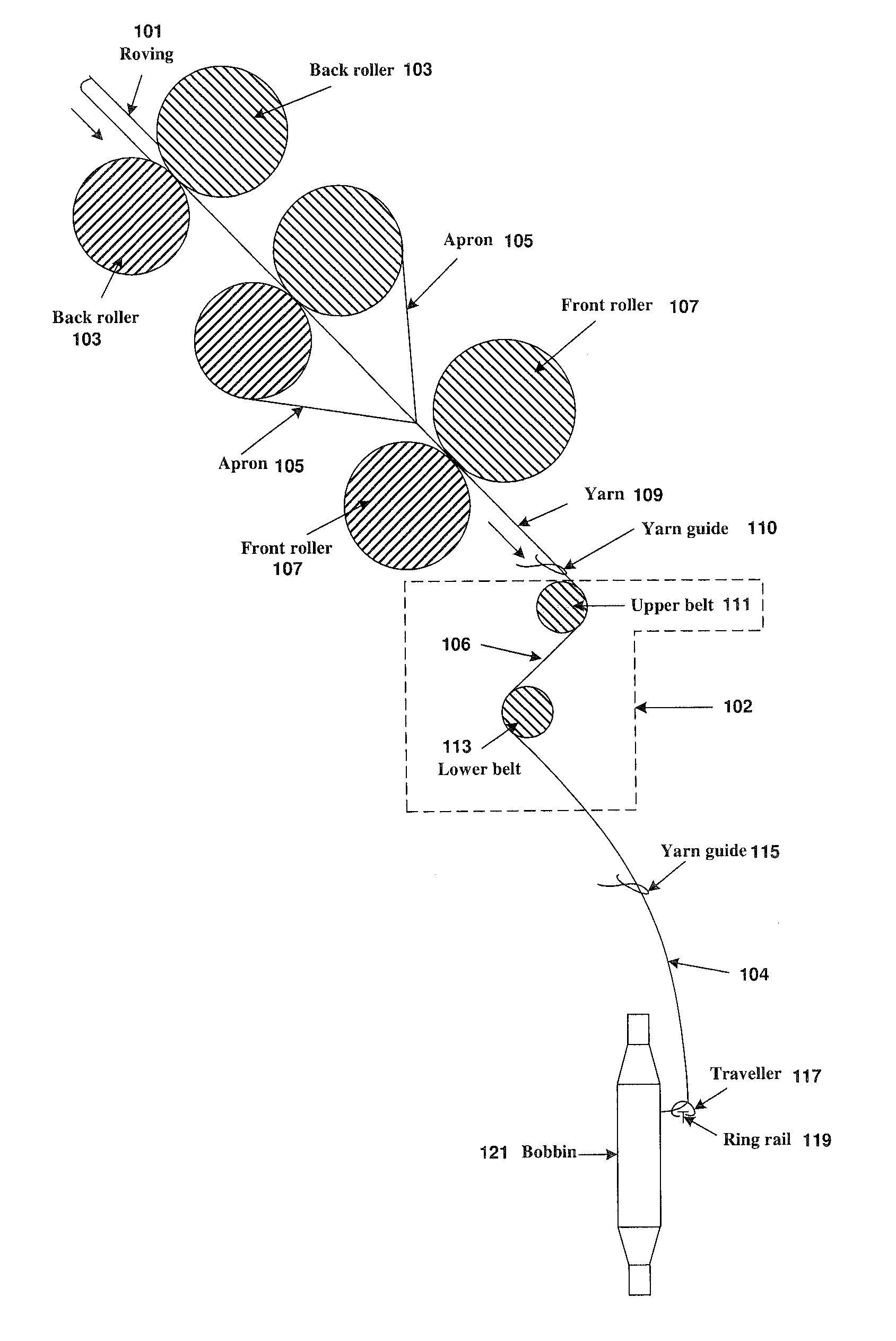
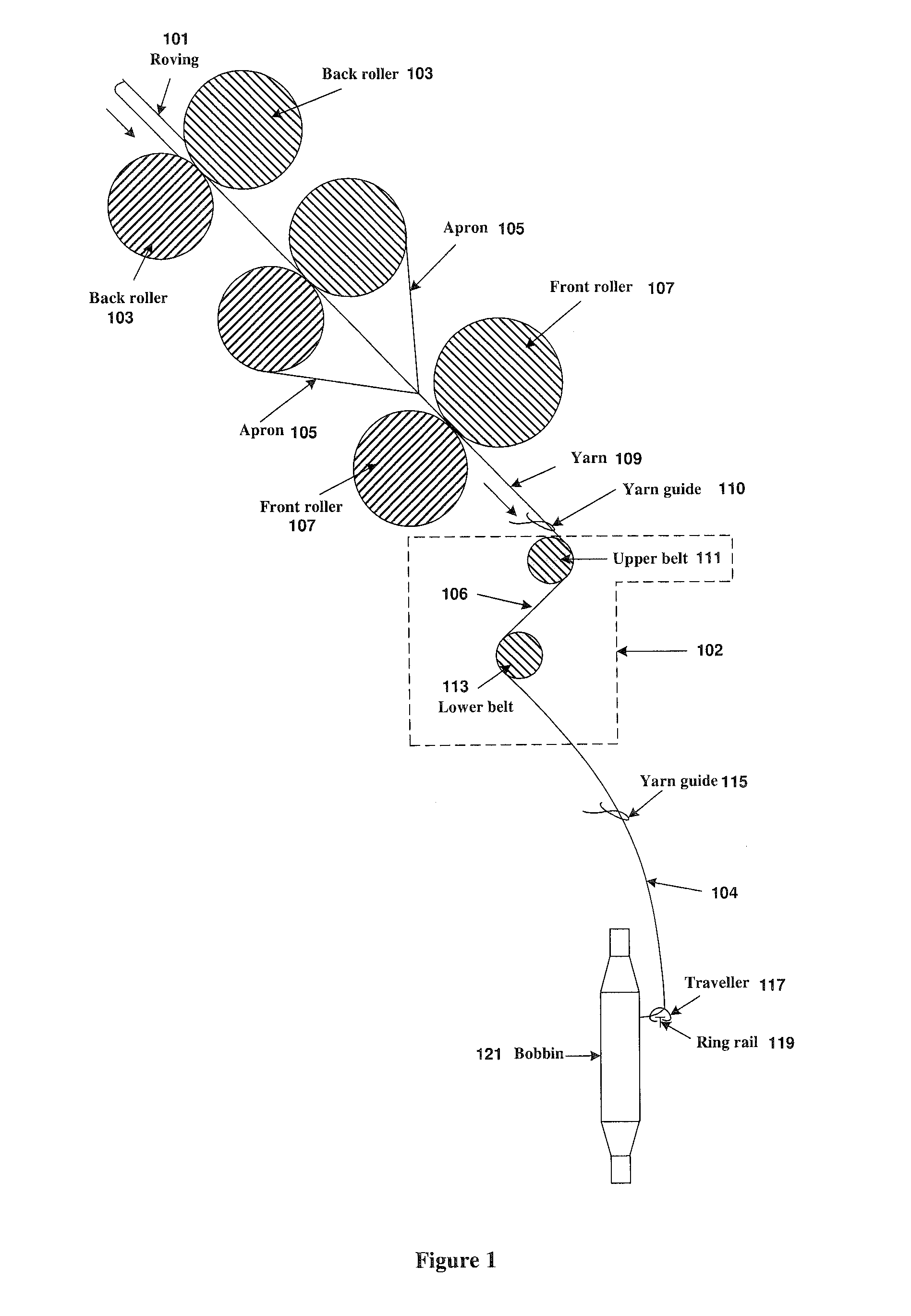
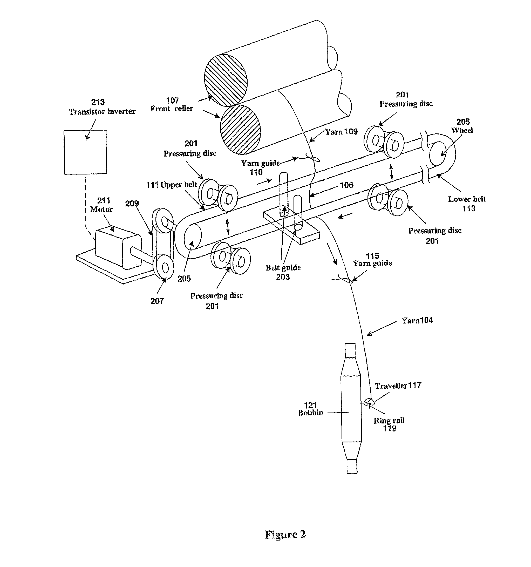
[0043]FIGS. 1 and 2 illustrate aside diagrammatic plan view and a schematic representation in perspective of a spinning apparatus in accordance with an exemplary embodiment of the present invention, respectively. As shown in FIGS. 1 and 2, a roving 101 is delivered through the drafting system 103, 105 and 107, including a pair of back drafting rollers 103, a pair of aprons 105, and a pair of front drafting rollers 107. The drafted roving is twisted by the upper belt 111 of a false twist device 102 to form a preliminary singles yarn wherein the false twist for a yarn is provided by the running action of the upper belt 111. Immediately after the false twist step by the upper belt 111 serving as the first twisting point, a joint twist of a second twist in the same direction as the first twist and a twist travel toward the region in the reversed direction are imparted to the preliminary singles yarn 106 for the production of a final singles ring yarn, wherein the second twist is produce...


PUM

PropertyMeasurementUnit
Fractionaaaaaaaaaa
Speedaaaaaaaaaa
Speedaaaaaaaaaa

Abstract

Method and apparatus for reducing residual torque in singles ring yarns, achieved by imparting two separate false twisting points on the traveling strand of fibers (or yarn) after the strand exits from the spinning triangle with a proper ratio between the belt speed and the strand feeding speed. In addition to reducing the residual torque, this double false twist technique also reduces yarn hairiness to the same level as achieved by more expensive compact spinning devices, reduces yarn twist by more than 20% and significantly enhances yarn and fabric softness. Furthermore, by combining the double false twist technique with a compact spinning device, the numbers of neps, thick and thin places are significantly reduced to produce high-quality yarns and fine-count yarns.

Description

CROSS-REFERENCE TO RELATED APPLICATION[0001]This application is a continuation-in-part (CIP) of prior application Ser. No. 12 / 222,133, filed on Aug. 4, 2008.FIELD OF THE INVENTION[0002]The present invention relates to spinning technology for the production of a singles ring yarn. The invention is particularly concerned with a method and apparatus that utilize a false twist device with two false twisting points to yarns between double belts and incorporate them in the conventional ring spinning machine to improve yarn properties and fabric performance as well as the efficiency of false twist and ease of operation. The false twist efficiency for yarn and thus the property of the final singles ring yarn can be controlled, resulting in yarns with reduced residual torque and twist. This invention further relates to a solution to problems of yarn appearance deterioration peculiar to yarns produced using the double false twisting techniques of the present invention. This solution is partic...

Claims


Application Information

Patent Timeline
IPC IPC(8): D01H7/52D01H7/02
CPCD01H1/11D01H13/08D01H7/923D01H5/28D02G3/328
Inventor TAO, XIAOMINGHUA, TAOXU, BINGANGFENG, JIE
Owner THE HONG KONG POLYTECHNIC UNIV
Learn More