A ring spinning frame spinning section strengthening device

A technology for strengthening device and spinning section, which is applied in the field of strengthening device for spinning section of ring spinning frame, which can solve the problems of weak control of twisting triangle area, increase of unit power consumption, easy occurrence of end breakage, etc., and achieve high false twisting efficiency , End-break reduction, and single-yarn twist reduction

Active Publication Date: 2016-06-08
WUXI YGM TEXTILE
View PDF4 Cites 0 Cited by
  • Summary
  • Abstract
  • Description
  • Claims
  • Application Information

AI Technical Summary

Problems solved by technology

[0002] During the twisting and winding process of the ring spinning frame, due to the effects of twist resistance and twist trapping, the average twist on the strands in the spinning section is about 5%-10% less than that of the finished yarn, and the spinning strength is only four times the strength of the finished yarn. One or so, the twist is less in the twisting triangle area, and there is almost no twist, which causes two problems. One is that the weak twist area in the spinning section is prone to broken ends; the other is that the control of the twisting triangle area is weak, causing Low yarn strength (the strength of the whole yarn is much smaller than the sum of the strength of all single fibers in the cross section), and there is much hairiness
At present, there are two solutions. One is to increase the yarn twist (true twist), but even within the critical twist, it will bring about adverse effects such as reduced per unit yield, increased unit power consumption, hard handle, and poor gloss; the second is False-twist devices are used in the spinning section, Feng Jiangnan, Huang Jianming, and Ni Yuan recorded in "Feasibility Analysis of the Industrial Application of Spinning False-twist Spinning Mechanisms" in "Cotton Textile Technology", Issue 3, 2013, pp. 59-64, and now There are six types of false twisting devices in the spinning section, but all of them have severe longitudinal sliding friction between the false twisting element and the sliver, causing additional damage to the sliver, which needs to be solved perfectly

Method used


Image

  • A ring spinning frame spinning section strengthening device
  • A ring spinning frame spinning section strengthening device
  • A ring spinning frame spinning section strengthening device

Examples


Embodiment Construction

[0026] The technical solutions of the present invention are further described below with reference to the accompanying drawings and through specific embodiments.

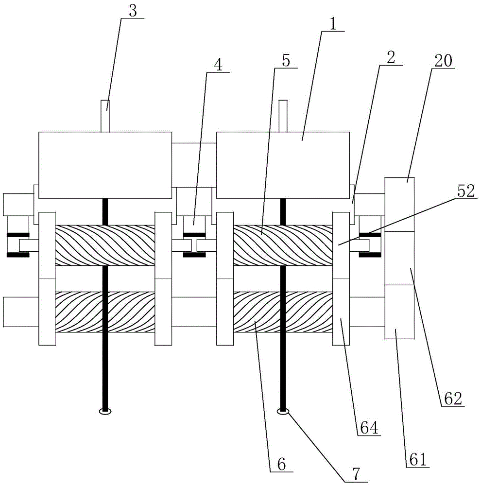
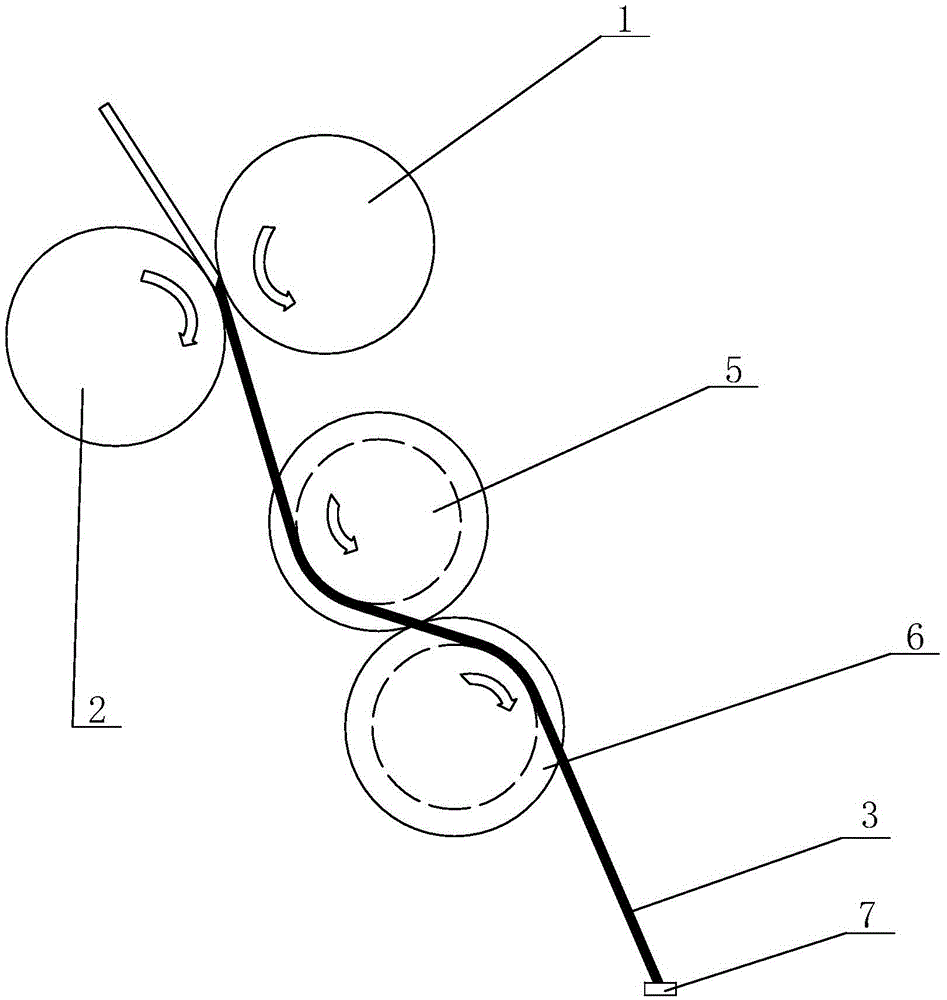
[0027] see Figure 1 to Figure 8 As shown, in this embodiment, a device for enhancing the spinning section of a ring spinning frame, taking Z-twisted yarn as an example, includes a front top roller 1 and a front roller 2, and the front top roller 1 and the front roller 2 form a yarn The front jaw of the bar 3, and one end of the front roller 2 is connected with a front roller gear 20, and a plurality of helical press rollers 5 are installed downstream of the front jaw through the helical press roller support 4. The helical press rollers 5 includes a pressure roller shaft 50 rotatably arranged on the spiral pressure roller support 4, a pressure roller sleeve 51 is detachably fixed on the pressure roller shaft 50, and the surface of the pressure roller sleeve 51 is provided with multiple heads Right helical pattern, ...


PUM

PropertyMeasurementUnit
widthaaaaaaaaaa
lengthaaaaaaaaaa
diameteraaaaaaaaaa

Abstract

The invention discloses a spinning section enhancing device for a ring spinning frame, belonging to the field of textile machinery. The spinning section enhancing device for the ring spinning frame comprises a front jaw consisting of a front leather roller and a front roller, wherein a spiral compression roller with a spiral thread on the surface is arranged in the downstream part of the front jaw through a spiral compression roller supporting piece, a spiral roller with a spiral thread on the surface is arranged in the downstream part of the spiral compression roller through a spiral roller supporting piece, and the spiral threads on the surfaces of the spiral roller and the spiral compression roller are opposite in direction. A sliver bypassing the spiral compression roller enters into the spiral roller, and the spiral roller and the spiral compression roller are connected with a driving part. When the spiral compression roller and the spiral roller rotate, the motion curves of the spiral lines on the surfaces can be divided into transverse and longitudinal sub motions, so that the silver is positively conveyed forward while being falsely twisted, thus, guaranteeing that the sliver is free from extra damage. Meanwhile, two false twisting contact sections are adopted, so that the false twisting efficiency is high, the lateral deviation is compensated, and the spinning section enhancing device is more convenient to operate and maintain due to the structure of the movable spiral compression roller.

Description

technical field [0001] The invention relates to the technical field of spinning, in particular to a spinning section strengthening device of a ring spinning frame. Background technique [0002] During the twisting and winding process of the ring spinning frame, the average twist on the whisker in the spinning section is about 5%-10% less than that of the finished yarn, and the spinning strength is only four times that of the finished yarn. About one, there is less twist in the twisting triangle area, and there is almost no twist, which causes two problems. One is that the weak twist area of ​​the spinning section is prone to breakage; the other is that the control force on the twisting triangle area is weak, causing The yarn strength is low (the strength of the whole yarn is far less than the sum of the strengths of all single fibers in the section), and there are many hairiness. At present, there are two solutions. One is to increase the twist of the finished yarn (true tw...

Claims


Application Information

Patent Timeline
Patent Type & Authority Patents(China)
IPC IPC(8): D01H1/11D01H7/92
Inventor 范琥跃周晔珺徐晖孙建平
Owner WUXI YGM TEXTILE
Why Eureka
Try Eureka