Encapsulated switchgear

a switchgear and encapsulation technology, applied in the direction of liquid handling, organic gas insulators, transportation and packaging, etc., can solve the problems of gas leakage, mechanical stress on the switchgear housing, and relatively complex equipment used for gas pressure measurement in general, and achieve simple and cost-effective design

Active Publication Date: 2012-06-21
ABB (SCHWEIZ) AG +1
View PDF3 Cites 11 Cited by
  • Summary
  • Abstract
  • Description
  • Claims
  • Application Information

AI Technical Summary

Benefits of technology

[0016]The object of the present invention is thus to provide an encapsulated switchgear which can be operated in an environmentally friendly manner and which at the same time allows for a very simple and cost-effective design by meeting highest safety requirements.

Problems solved by technology

The equipment used for gas pressure measurement is in general relatively complex and expensive.
Due to this overpressure, the housing of the switchgear can be subject to mechanical stress and therefore be prone to gas leakage if appropriate technical measures are not taken.
However, the demands on the gas-tightness of the currently used switchgears are very strict, because conventional insulation gases with a high insulation and arc extinction performance have some environmental impact when released to the atmosphere and, in particular, have a relatively high global warming potential (GWP).
The construction of the housing of a switchgear is thus relatively complex, which—in addition to the expensive gas pressure measurement equipment—further contributes to the relatively high cost of conventional switchgears.
Also, if high amounts of the insulation gas leak out of the housing, the reaction time for establishing sufficient insulating properties is often relatively long.

Method used


Image

  • Encapsulated switchgear
  • Encapsulated switchgear
  • Encapsulated switchgear

Examples


Embodiment Construction

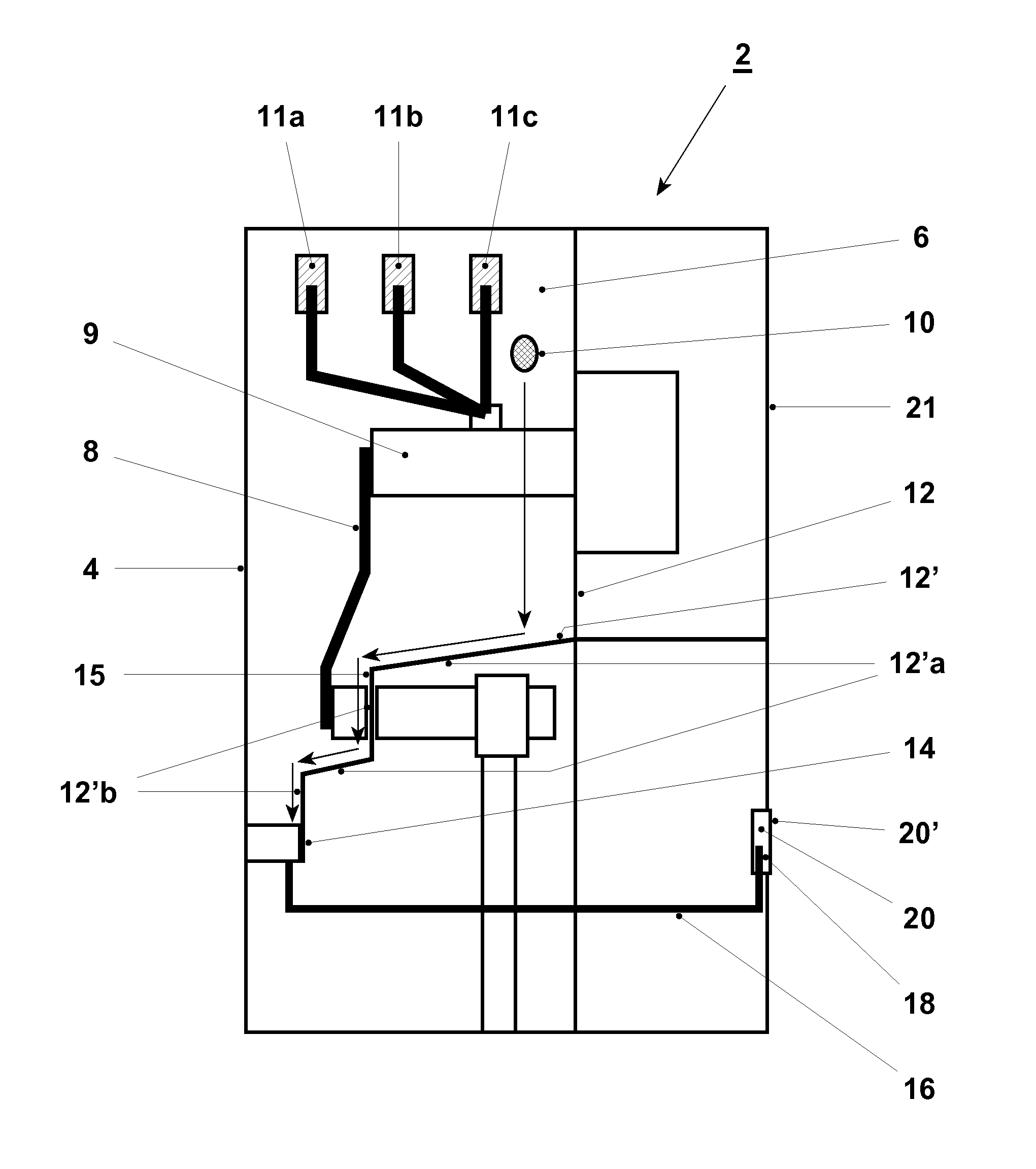
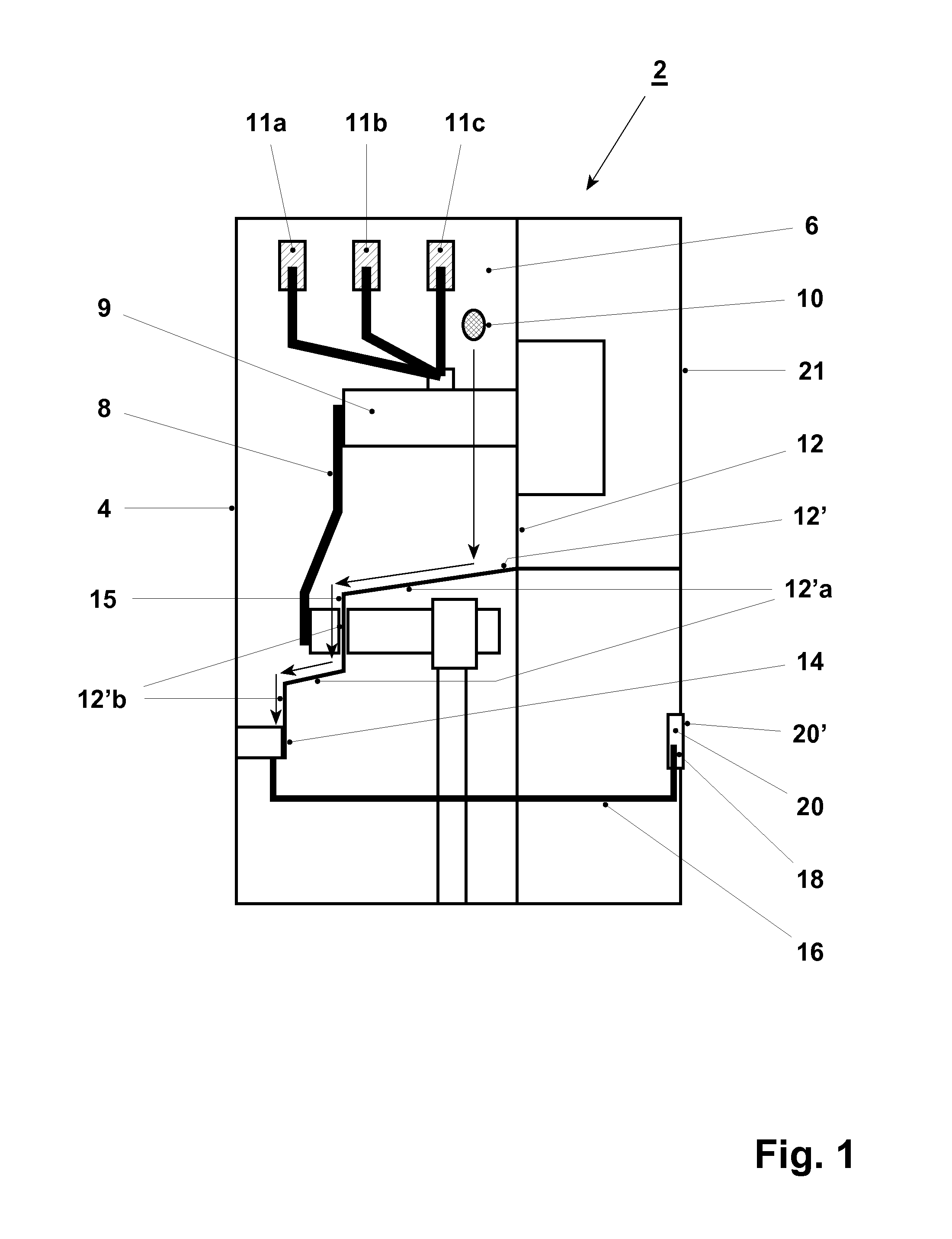
[0055]According to FIG. 1, the switchgear 2 comprises a housing 4 defining an insulating space 6 and an electrical active part 8 arranged in the insulating space 6. In the embodiment shown, the electrical active part 8 comprises a switch element 9 and three bus bars 11a, 11b, 11c connected to the switch element 9. The insulating space 6 comprises an insulation medium comprising an insulation gas. Said insulation gas comprises a gaseous part of a dielectric compound which is in equilibrium with a liquid part of the dielectric compound.

[0056]Droplets 10 of the liquid part condensed on the walls 12 of the housing 4 flow or fall downwards in direction to the bottom wall 12′ (as indicated by an arrow). In the embodiment given in FIG. 1, the bottom wall 12′ has a stepwise configuration, wherein segments 12′ a inclined, in particular weakly inclined, downwards alternate with strongly inclined, in particular vertical, segments 12′ b, and leads to a receptacle 14. Thus, the liquid collected ...


PUM


Abstract

An encapsulated switchgear that includes a housing defining, an insulating space, and an electrical active part arranged in the insulating space, the insulating space with an insulation medium. The switchgear is characterized in that the insulation medium with a dielectric compound having a boiling point of above −25° C.

Description

CROSS-REFERENCE TO RELATED APPLICATIONS[0001]The present application is a continuation of pending International patent application PCT / EP2009 / 062640 filed on Sep. 29, 2009 which designates the United States and which is a continuation of International patent application No. PCT / EP2009 / 057294 filed on Jun. 12, 2009. The content of all prior applications is incorporated herein by reference.FIELD OF THE INVENTION[0002]The present invention relates to an encapsulated switchgear, to a process for providing an encapsulated switchgear, and to the use of a dielectric compound having a boiling point of above −25° C. in an insulation medium for an encapsulated switchgear, in particular a medium voltage encapsulated switchgear.BACKGROUND OF THE INVENTION[0003]In medium or high voltage encapsulated switchgears, the electrical active part is arranged in a gas-tight housing, which defines an insulating space, said insulating space usually comprising an insulation gas and separating the housing fr...

Claims


Application Information

Patent Timeline
Patent Type & Authority Applications(United States)
IPC IPC(8): H01H33/66B65B31/00
CPCH01B3/56H01H11/00H01H9/02H02B13/055H01H33/56H02B13/00
Inventor HYRENBACH, MAIKGRANHAUG, OLECLAESSENS, MAX-STEFFENSKARBY, PER
Owner ABB (SCHWEIZ) AG
Why Eureka
Try Eureka