Motor noise reduction circuit

a noise reduction and motor technology, applied in speech analysis, color television, television systems, etc., can solve the problems of user hearing, built-in feature, and rather expensive way of achieving this effect by using quieter zoom and focus motors, and achieve the effect of reducing nois

Active Publication Date: 2012-06-21
MICROSEMI SEMICON
View PDF8 Cites 21 Cited by
  • Summary
  • Abstract
  • Description
  • Claims
  • Application Information

AI Technical Summary

Benefits of technology

[0010]Thus, according to the present invention there is provided a method of reducing noise in an environment where the noise source is in a fixed location relative to a pair of microphones, comprising receiving signals x1(t), x2(t) from the respective microphones; and filtering each of the signals x1(t), x2(t) with respective first and second linear filters having filter coefficients obtained by computing eigenfilters corresponding to data samples from the respective microphones for noise only and signal only conditions.
[0012]An advantage of the embodiments of invention is that they consume very low MIPs, (around 3 MIPS, assuming 48000 sampling rate); also they can significantly reduce effective noise by more than 15 dB with minimum degradation and very low distortion of the input audio signal. In one embodiment, the method is based on TISO (two-input, single output) linear filtering of the two microphone signals.
[0014]Thus the invention relates to a method for reducing zoom or focus motor noise picked up by camera's microphones during video recording. Noise is reduced by digital processing of the outputs of the two microphones on the camera. The noise is reduced using an Eigenfiltering approach where the two microphone signals are combined through linear filters in such way to minimize the noise and maintain the desired output audio signal. These linear filters may be implemented as part of the firmware running on the camera's internal processor while the coefficients for these linear filters may be calculated offline in advance (e.g. on a PC) based on following steps.

Problems solved by technology

Most cameras with this built-in feature suffer from the problem of the user hearing the sound of the zoom motor picked up by on-camera microphones.
A rather expensive way of achieving this result is to use quieter zoom and focus motors.
This may not be a cost effective solution, especially for low cost cameras.
The main challenge is that removing the motor noise should not distort input audio signal.
As a result, such noise cannot be eliminated using traditional DSP filtering techniques (e.g. lowpass filtering, notch filter etc.).
Also single microphone noise reduction methods which rely on subtracting noise spectrum from the input signal spectrum are not very attractive since they tend to distort the original audio signal.
To make matters worse, the spectrum of motor noise may change with time.
This can affect the performance of the algorithms that mainly rely on a stationary noise assumption.
Other approaches such as beamfoming and active noise control (ANC) have their own limitations.
Also beamforming or similar approaches may require a greater number of microphones (more than two) which may not feasible on a small camera body.
In addition, these methods are usually computationaly expensive to implement.

Method used


Image

  • Motor noise reduction circuit
  • Motor noise reduction circuit
  • Motor noise reduction circuit

Examples


Embodiment Construction

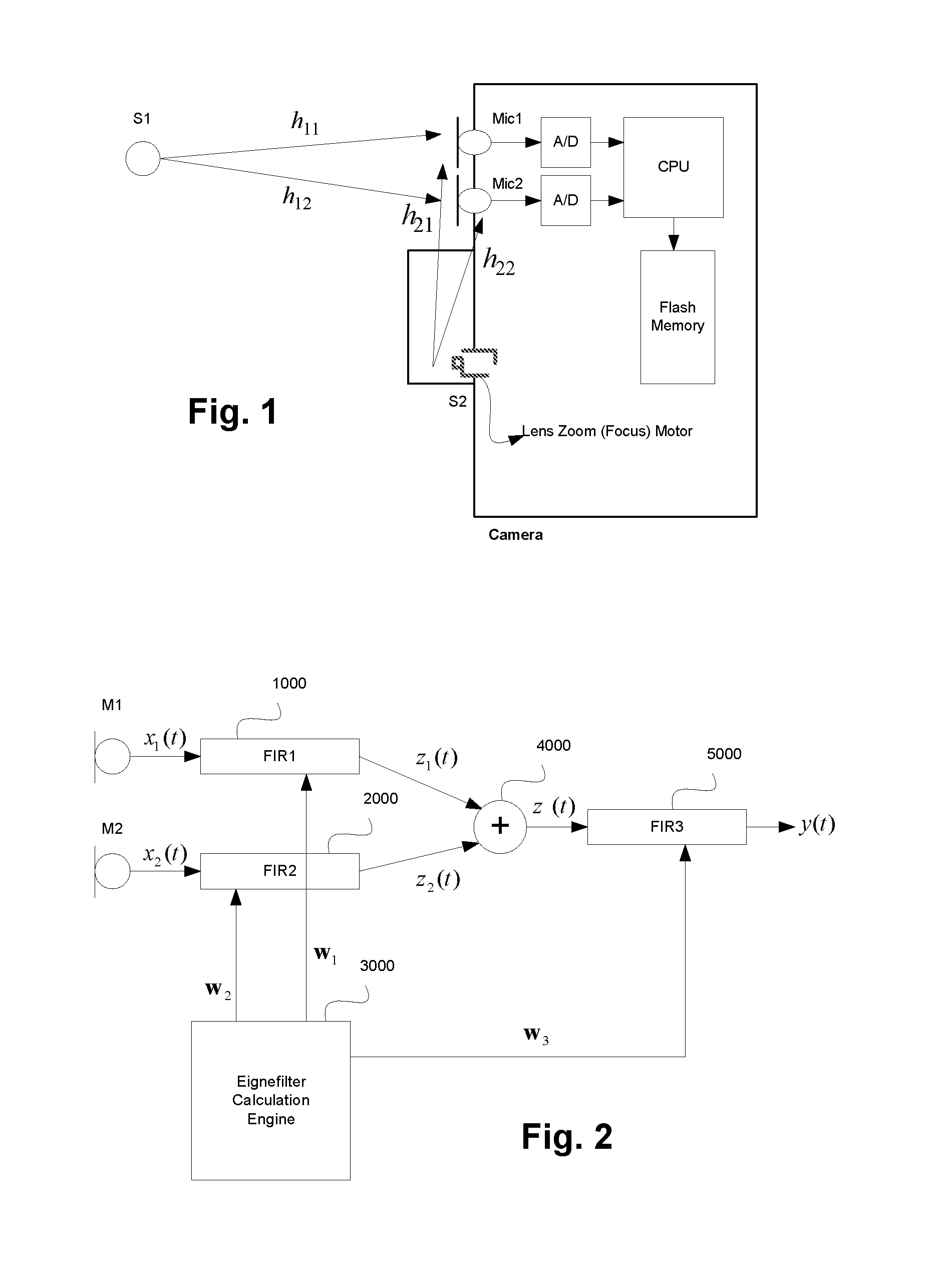
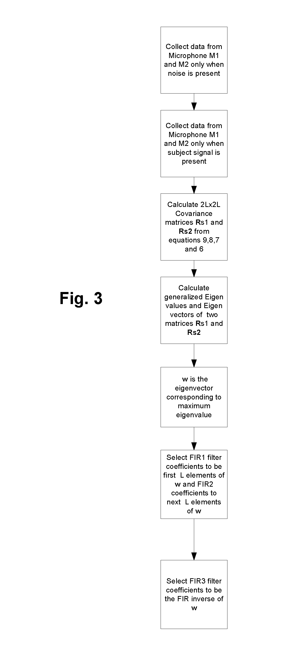
[0032]The invention will be explained in detail using the following notation throughout the description:

t is the index to a sample.

x1 (t) is the digitized signal from microphone M1.

x2(t) is the digitized signal from microphone M2.

z1(t) is the output of the first FIR filter with input xj(t).

z2(t) is the output of the second FIR filter with input x2(t).

z(t) is the output summation of z1(t) and z2(t).

y(t) is the output of the third FIR filter with input z(t).

w1(k) are the filter coefficients for the first FIR filter.

w2(k) are the filter coefficients for the second FIR filter.

w3(k) are the filter coefficients for the third FIR filter.

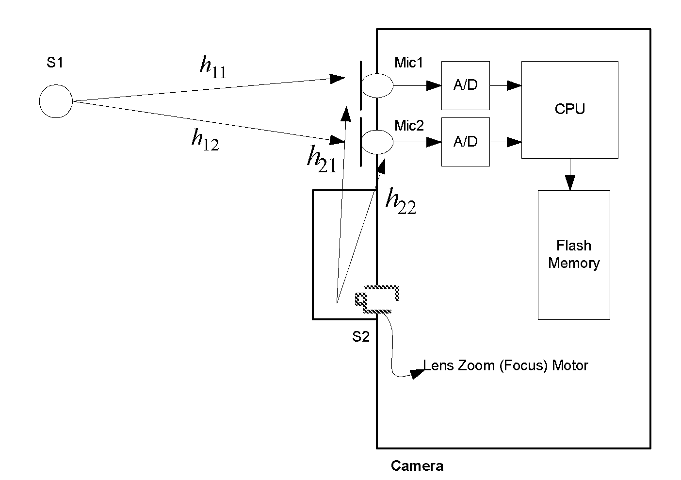
[0033]Consider a video camera as shown in FIG. 1 and let x1(t) represent the output signal of microphone (M1) and x2(t) represent the output signal of microphone (M2). In this case, the following relationship holds:

[x1(t)x2(t)]=[h11h12h21h22][s1(t)s2(t)](1)

where S1(t) represents the equivalent time domain signal of the subject which is the desired signal an...


PUM


Abstract

A method of reducing noise in an environment where the noise source is in a fixed location relative to a pair of microphones, such as in a camera with a zoom motor, involves receiving signals x1(t), x2(t) from the respective microphones, and filtering each of the signals x1(t), x2(t) with respective first and second linear filters having filter coefficients obtained by computing eigenfilters corresponding to data samples from the respective microphones for noise only and signal only conditions.

Description

FIELD OF THE INVENTION[0001]This invention relates to the field of digital signal processing, and in particular to a method and apparatus for the reduction of noise in an environment having a fixed noise source, such as a camera zoom lens motor.BACKGROUND OF THE INVENTION[0002]In digital cameras with video recording capability, one of the desired features is the ability to zoom and focus while video recording. Most cameras with this built-in feature suffer from the problem of the user hearing the sound of the zoom motor picked up by on-camera microphones.[0003]FIG. 1 is a simple block diagram of the camera where Mic1 and Mic2 are the two microphones used on the camera for audio stereo recording, S1 represents the desired voice or audio signal that should be recorded by the camera with minimum distortion and S2 represents the audio noise generated by the zoom or lens focus motor. Also in this figure, h21 and h22 represent the acoustic paths between the motor and the two microphones. ...

Claims


Application Information

Patent Timeline
Patent Type & Authority Applications(United States)
IPC IPC(8): H04N5/225H04B15/00
CPCH04R3/005H04R2430/20G03B31/00G10L21/0264G10L2021/02166G10L21/0224
Inventor RAHBAR, KAMRANMORGAN, DEAN
Owner MICROSEMI SEMICON
Why Eureka
Try Eureka